Memory controller and memory control method

a memory controller and controller technology, applied in the field of memory controller and memory control method, can solve the problems of unintentional overwriting of data, increase in write data amount, and inapplicability to writing operations, and achieve the effect of reducing or eliminating the influence of a comparatively long penalty

Active Publication Date: 2022-07-21
CANON KK
View PDF0 Cites 0 Cited by
  • Summary
  • Abstract
  • Description
  • Claims
  • Application Information

AI Technical Summary

Benefits of technology

[0014]A mode of the present invention provides a technique that can reduce or eliminate the influence of a comparatively long penalty that accompanies the issuance of a write command for writing, into a DRAM, data having a length which is less than a predetermined length.
[0017]A mode of the present invention reduces or eliminates the influence of a comparatively long penalty that accompanies the issuance of a write command for writing, into a DRAM, data having a length which is less than a predetermined length.

Problems solved by technology

However, the method disclosed in Japanese Patent-Laid Open No. 2005-182538 is problematic in that data will be unintentionally overwritten or the write data amount will increase because of the addition of the dummy data.
Also, the method disclosed in Japanese Patent-Laid Open No. 2005-182538 is not applicable to a writing operation, that is, a partial write operation, for rewriting only a partial area within the length per access.

Method used


Image

  • Memory controller and memory control method
  • Memory controller and memory control method
  • Memory controller and memory control method

Examples


first embodiment

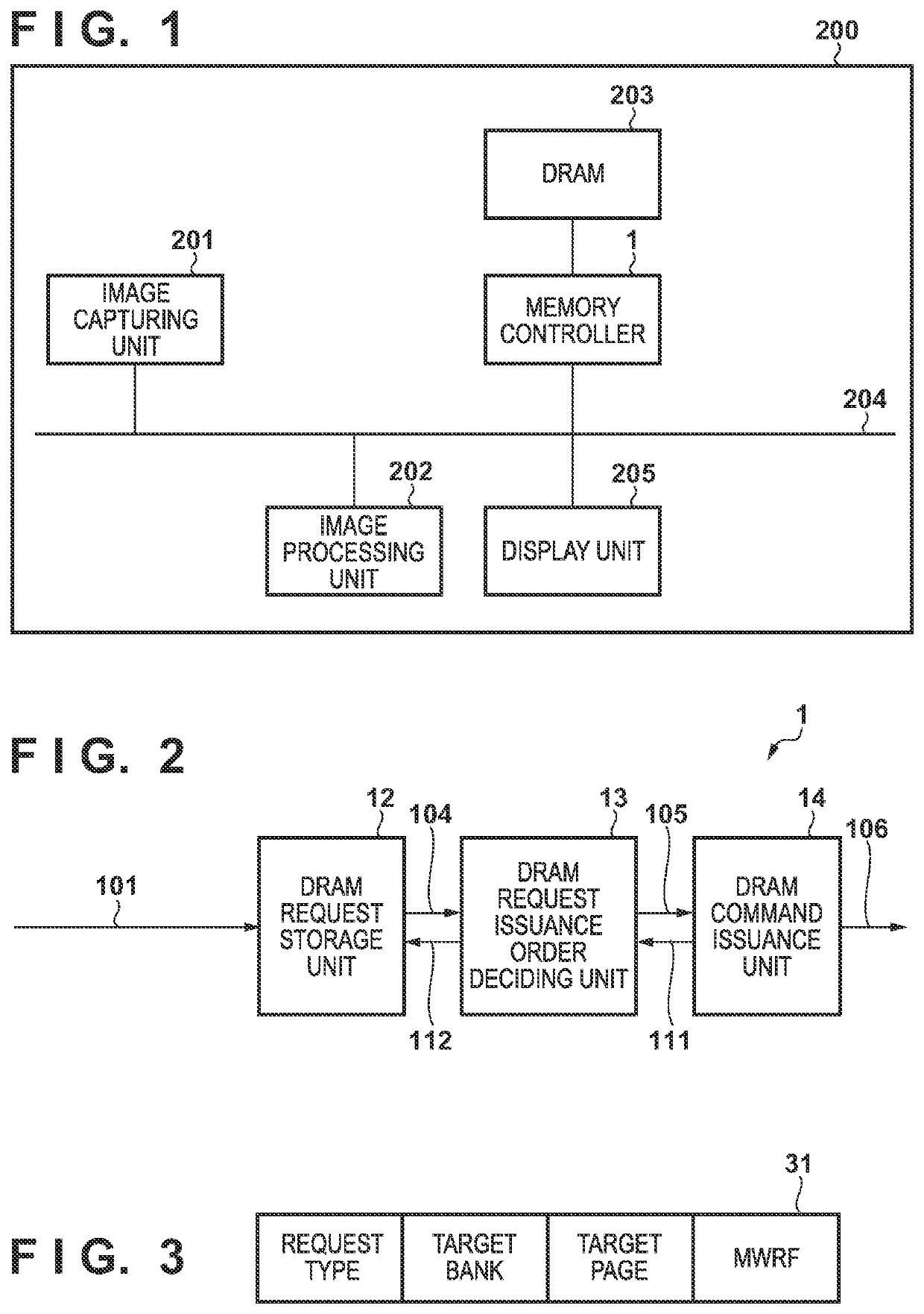
[0031]FIG. 1 is a block diagram showing the hardware arrangement of an image processing apparatus 200 including a memory controller 1 according to the first embodiment. The image processing apparatus 200 is a small electronic device, for example, a smartphone or the like. The image processing apparatus 200 has a function of capturing an image of an object and displaying the captured image on a monitor in real time. Note that a case in which the image processing apparatus 200 incorporates the memory controller 1 according to the first embodiment will be described hereinafter. However, it should be obvious to a person skilled in the art who has read this specification that the memory controller 1 can be widely incorporated to general electronic devices such as a digital camera and the like.

[0032]The image processing apparatus 200 includes at least an image capturing unit 201, a DRAM 203, an image processing unit 202, a system bus 204, and the memory controller 1.

[0033]The image captur...

second embodiment

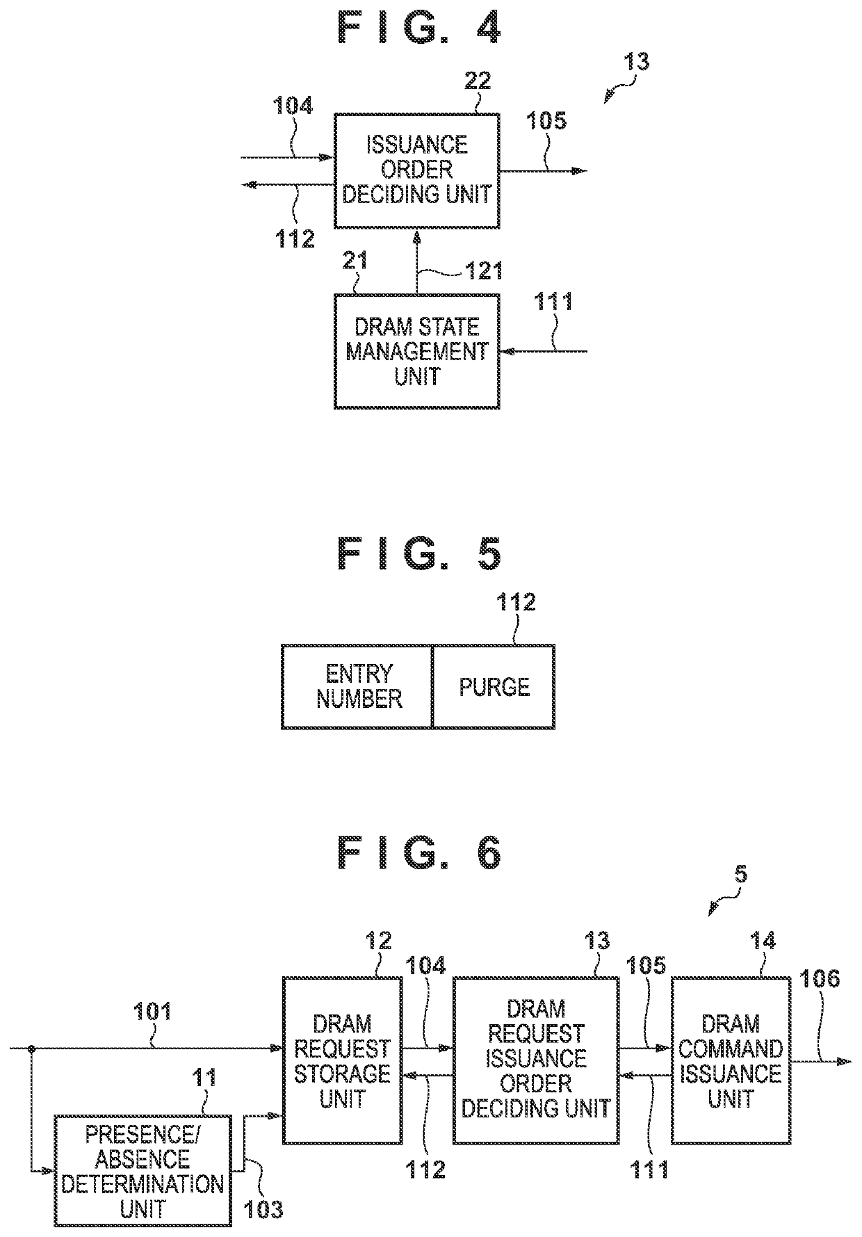
[0162]FIG. 6 is a block diagram showing the function and the arrangement of a memory controller 5 according to the second embodiment. The memory controller 5 according to this embodiment includes, in addition to a memory controller 1 according to the first embodiment, an MWR command presence / absence determination unit 11. Also, in a similar manner to the first embodiment, assume that a WR command is used as a first write command for writing data which has a predetermined length in a DRAM 203 and an MWR command is used as a second write command for writing data which is less than a predetermined length in the DRAM 203.

[0163]Note that a single DRAM request 101 was executed by a single DRAM command in the first embodiment. However, in the second embodiment, the single DRAM request 101 can be executed by a DRAM command string formed from a plurality of DRAM commands.

[0164]The memory controller 5 according to this embodiment will be described in detail with reference to FIG. 6. Functions...


PUM


Abstract

A memory controller that is formed to be able to issue a first write command for writing data of a predetermined length into a DRAM and a second write command for writing data which is less than the predetermined length in the DRAM is provided. The memory controller comprises a deciding unit configured to decide an issuance order of a request stored in the storage unit. In a period from the issuance of a preceding DRAM command until a second write command targeting the same bank as the preceding DRAM command is issued, if another DRAM command targeting a bank different from the bank targeted by the preceding DRAM command can be issued, the deciding unit will decide the issuance order so that the other DRAM command that can be issued will be issued before the second write command.

Description

CROSS-REFERENCE TO RELATED APPLICATION[0001]This application is a continuation of U.S. patent application Ser. No. 17 / 004,240, filed on Aug. 27, 2020, which is hereby incorporated by reference herein in its entirety.BACKGROUND OF THE INVENTIONField of the Invention[0002]The present invention relates to a memory controller and a memory control method performed in the memory controller.Description of the Related Art[0003]There are many kinds of memory devices, such as a DRAM (Dynamic Random Access Memory), which are used in a memory system of an information processing apparatus. Among the memory devices, the DRAM is the most frequently used memory device.[0004]A DRAM has a large storage capacity per chip compared to other memory devices. It is also more inexpensive than other memory devices of the same capacity. Hence, a large-capacity memory system can be constructed inexpensively by using a DRAM. Therefore, the DRAM is widely used in memory system construction.[0005]In LPDDR4, which...

Claims


Application Information

Patent Timeline
Patent Type & Authority Applications(United States)
IPC IPC(8): G06F3/06G11C11/406
CPCG06F3/0659G06F3/0658G06F3/0653G06F3/0629G06F3/0614G06F3/0679G11C11/40622G11C11/4096G11C11/409Y02D10/00
Inventor ITO, MOTOHISASHIRAISHI, DAISUKE
Owner CANON KK
Why Eureka
Try Eureka