Detection Device
a detection device and detection technology, applied in the field of detection devices, can solve the problems that existing collection detection devices may not be able to accurately read tests, and achieve the effects of reducing or eliminating the influence of external factors, reducing production costs and assembly costs, and facilitating the use of collection detection devices
- Summary
- Abstract
- Description
- Claims
- Application Information
AI Technical Summary
Benefits of technology
Problems solved by technology
Method used
Image

Examples
embodiment 1
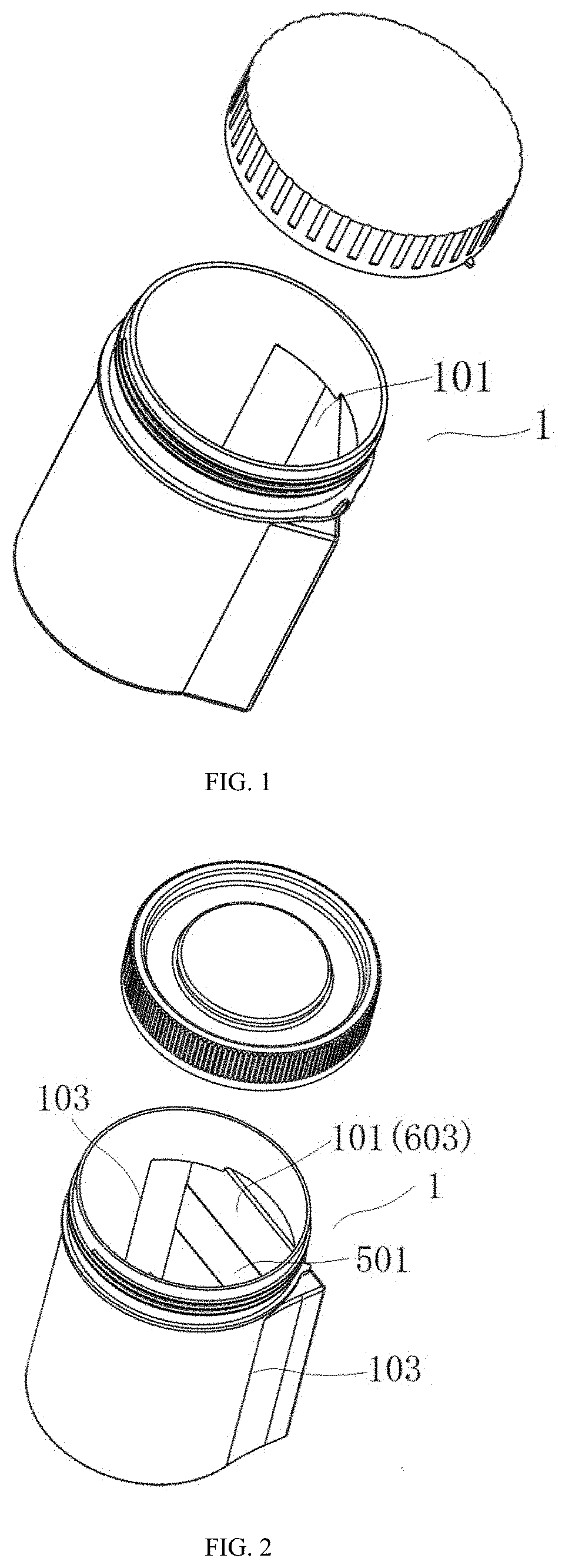
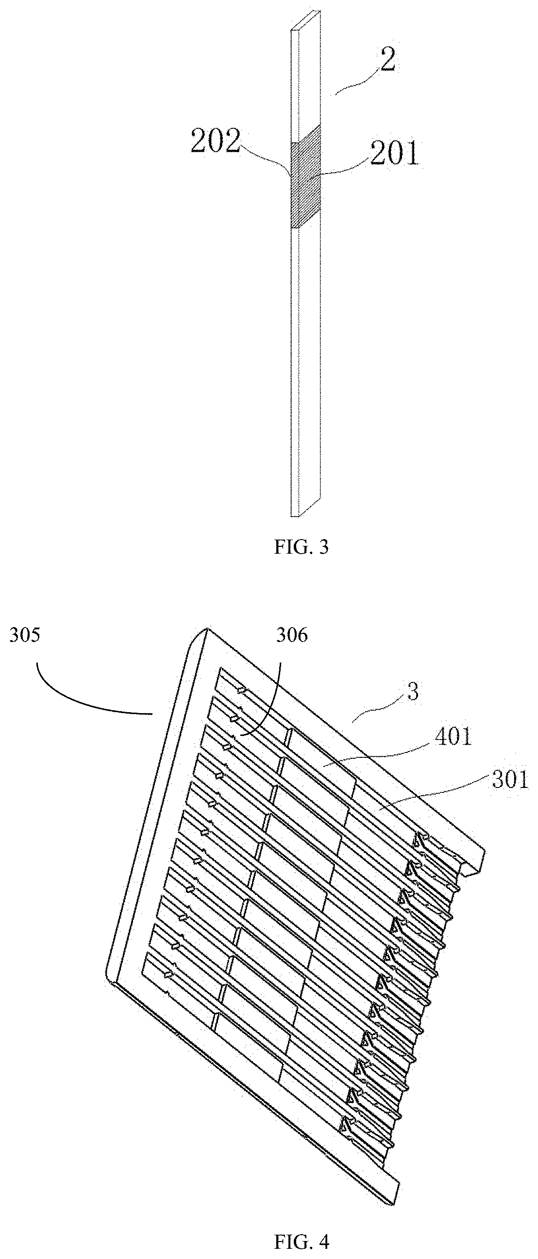
[0142]A detection device comprises a collecting chamber 1, for example as shown in FIG. 1, a testing element 2, for example as shown in FIG. 3, and a carrier 3 of the testing element, for example as shown in FIG. 4 The testing element 2 has a detection area 201, and the carrier 3 of the testing element has a groove 301 for accommodating the testing element and a bump 4 is arranged in the groove 301; and the detection area is arranged on the bump 4, and the side of the detection area with test reagents (such as antibodies, chemical substances, or antigens) faces upward, the reagents contact with an analyte in the sample as to indirectly or directly detect a presence of the analyte in the sample. The height 306 of the difference in distance between the bump 4 and the depth of the groove 305 is nearly equal to or slightly smaller than the thickness of the test area 201. The test area is generally composed of absorbent materials. In this way, the detection area 201 is arranged on the bu...
embodiment 2
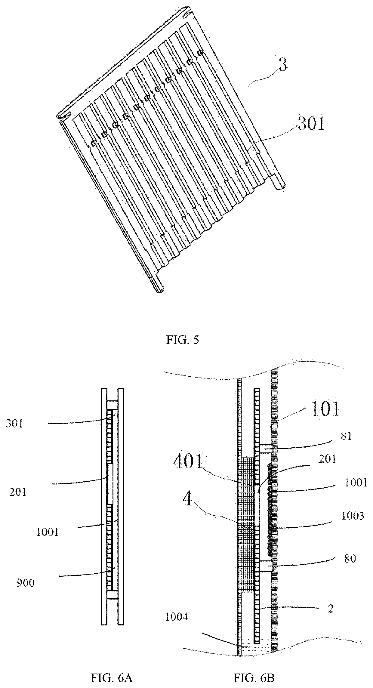
[0152]A detection device comprises a collecting chamber 1, for example as shown in FIG. 2, a testing element 2, for example as shown in FIG. 3, and a carrier 3 of the testing element, for example as shown in FIG. 5; the testing element 2 has a detection area 201, and the carrier 3 of the testing element has a groove 301 for accommodating the testing element, a bulge 5 is arranged in the collecting chamber 101, when the testing element is installed in the collecting chamber, the detection area 201 is clamped between the bulge 5 and the groove 301, and the detection area is attached to the bulge, for example as shown in FIG. 8 and FIG. 9. At this time, it can be understood that the testing element is inside the groove, when the carrier gets closes to the inner wall 101 of the collecting chamber, a part of the bump 5 enters into the groove and contacts with the test area on the testing element arranged in the groove, thereby making the test area 201 attached to the bump 5. At this time...
embodiment 3
[0157]The embodiments are the combination of embodiment 1 and embodiment 2. An anti-mist detection device, comprises a collecting chamber 1, for example as shown in FIG. 2, a testing element 2, for example as shown in FIG. 3, and a carrier 3 of the testing element, for example as shown in FIG. 4; the testing element 2 has a detection area 201, and the carrier 3 of the testing element has a groove 301 for accommodating the testing element, a bump 4 is arranged in the groove 301, and a bulge 5 is arranged on the inner wall of the collecting chamber; when the testing element 2 is combined with the collecting chamber 1, the bulge 5 is arranged facing the bump 4 and the detection area 201 is arranged between the bulge 5 and the bump 4, and the detection area 201 is attached to the bulge 5, for example as shown in FIG. 10 and FIG. 11.
[0158]One side of the bump 4 is connected to the groove, and the other side of the bump 4 is a free end 401; when the testing element 2 is combined with a co...
PUM
| Property | Measurement | Unit |
|---|---|---|
| distance | aaaaa | aaaaa |
| temperature | aaaaa | aaaaa |
| temperature | aaaaa | aaaaa |
Abstract
Description
Claims
Application Information
 - R&D
- Intellectual Property
- Life Sciences
- Materials
- Tech Scout
- Unparalleled Data Quality
- Higher Quality Content
- 60% Fewer Hallucinations
Browse by: Latest US Patents, China's latest patents, Technical Efficacy Thesaurus, Application Domain, Technology Topic, Popular Technical Reports.
© 2025 PatSnap. All rights reserved.Legal|Privacy policy|Modern Slavery Act Transparency Statement|Sitemap|About US| Contact US: help@patsnap.com