Laser guided patient positioning system for chiropractic x-rays and method of use

a positioning system and chiropractic x-ray technology, applied in the field of laser guided patient positioning system for chiropractic x-rays and methods of use, x-rays, can solve the problems of compromising the effectiveness of radiographic diagnosis, pain and ailment throughout the body, and the current radiographic method of chiropractic diagnosis, particularly of the upper cervical spine, to achieve the effect of improving the objectivity of this method, facilitating the subsequent analysis, and improving the accuracy of films

Active Publication Date: 2011-12-29
VAZQUEZ DAVID
View PDF2 Cites 6 Cited by
  • Summary
  • Abstract
  • Description
  • Claims
  • Application Information

AI Technical Summary

Benefits of technology

[0019]It is an object of this invention to provide a system and method for exact positioning of patients for radiography by using a system of lasers to reduce or eliminate the influence of positioning errors.
[0040]The laser unit has on one surface a mechanism for articulating with the undersurface of the track, which allows it to traverse or glide across the full length of the track. This mechanism also allows for locking of the laser unit in place once the desired position is reached. Along its track-articulating mechanism, the laser unit has a mark that is juxtaposed with the graduated distance markings along the track and also coincides with the center point of the laser crosshair. This allows the operator to measure the location of crosshair center point as a distance from the center of the grid cabinet.

Problems solved by technology

As such, the effectiveness of radiographic diagnosis is often compromised because it can be difficult to get the patient in just the right position and to orient the x-ray machine accordingly to take clear x-ray images.
In chiropractic, subluxation is a physical misalignment that distorts the body, causing the spine to deviate from its normal position, which can result in pain and ailment throughout the whole body.
Current radiographic methods for chiropractic diagnosis, particularly of the upper cervical spine, based on taking the x-ray views described above, suffer from inaccuracies due to the subjective positioning of the patient from view to view.
This results in radiographic images that can be inaccurate or unclear.
These methods do not consider active biomechanical dysfunction.

Method used


Image

  • Laser guided patient positioning system for chiropractic x-rays and method of use
  • Laser guided patient positioning system for chiropractic x-rays and method of use
  • Laser guided patient positioning system for chiropractic x-rays and method of use

Examples


Embodiment Construction

[0054]As shown in the drawings, a laser system according to an embodiment of the present invention is associated with a radiographic apparatus typically used for taking upper cervical x-rays. However, it will be understood that the system and method described herein can be used with any medical, industrial, and other type of x-ray machines where precise alignment of the subject is required.

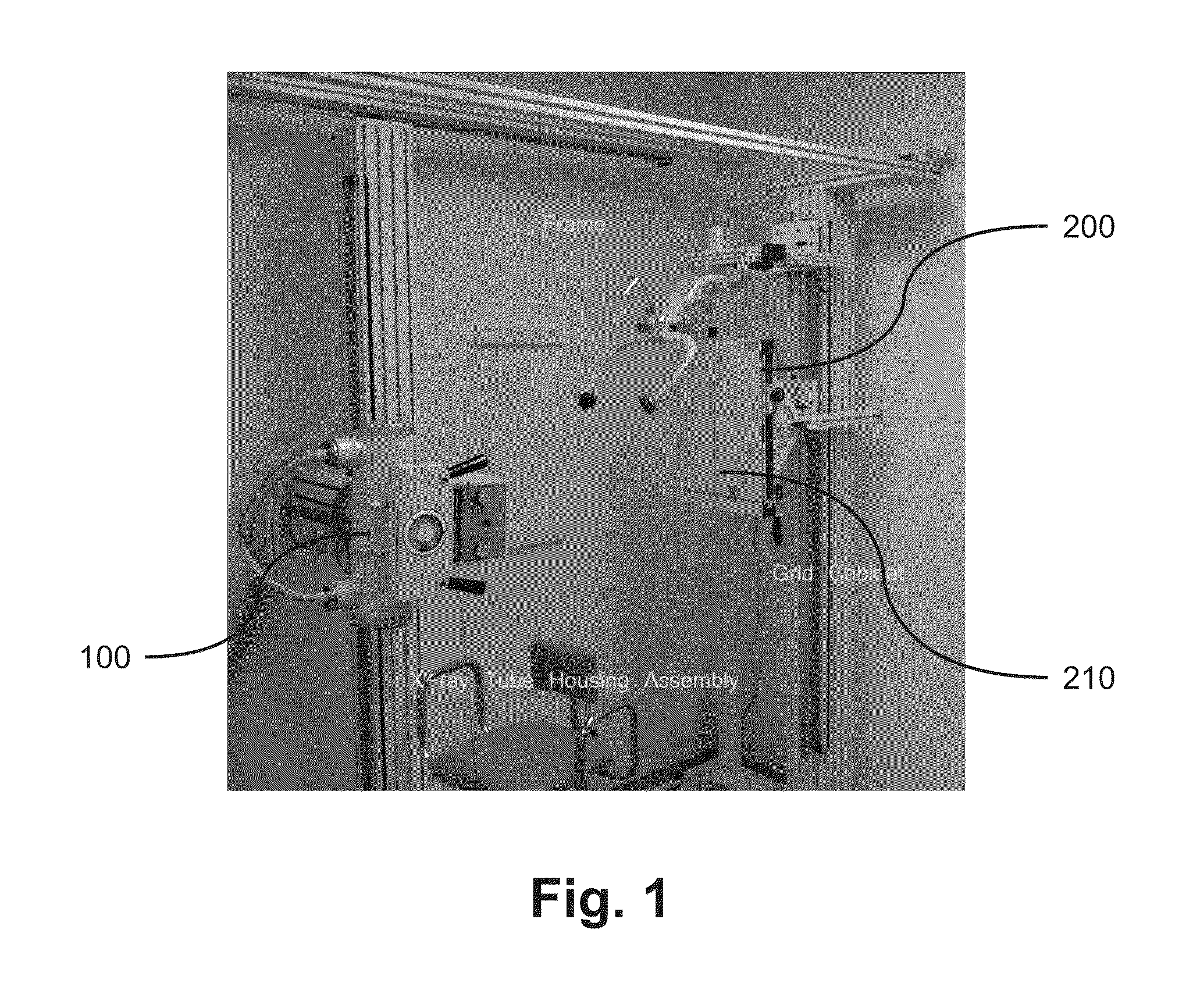
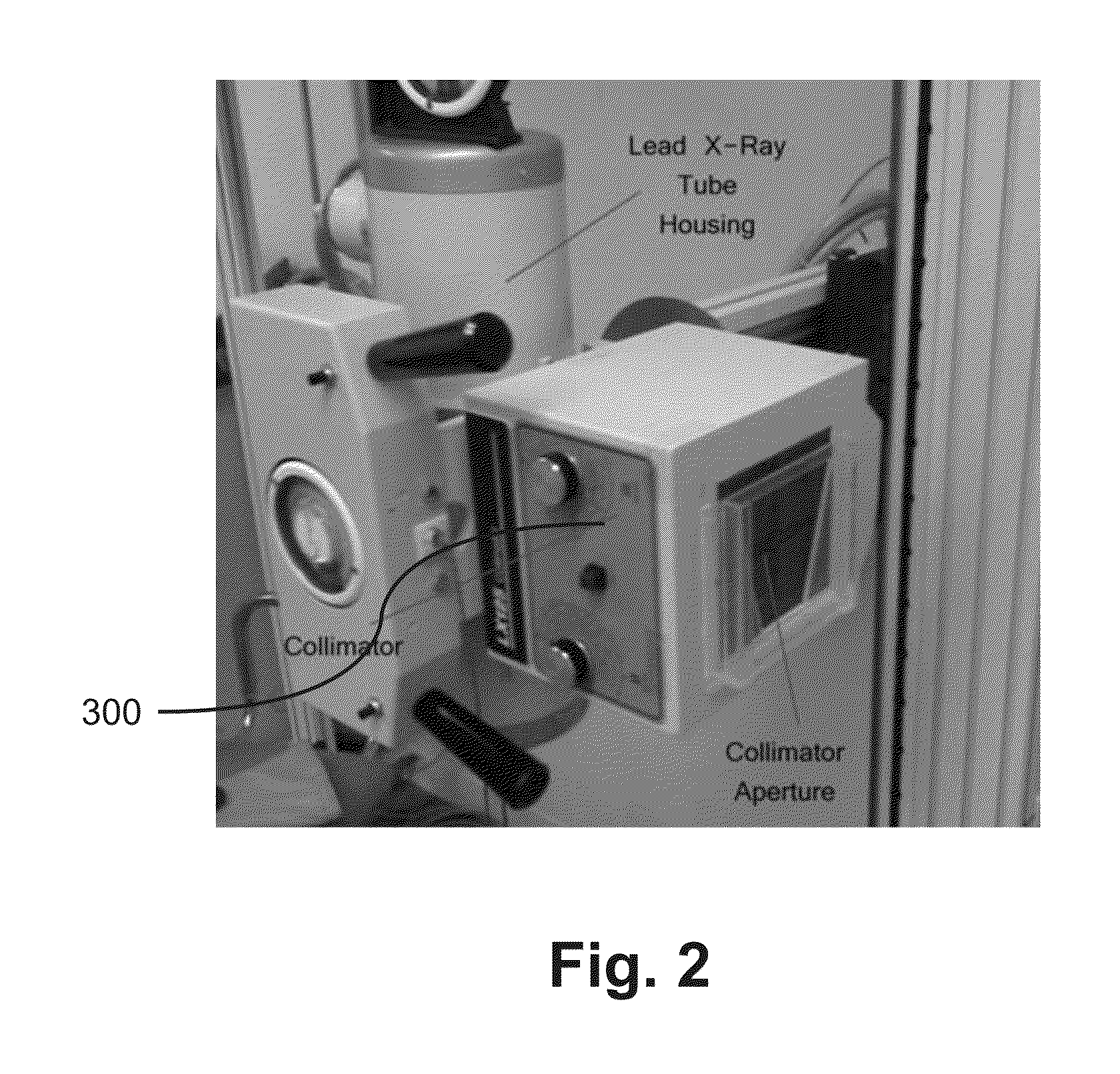
[0055]In a preferred embodiment of the invention as shown in FIG. 1, a radiographic apparatus 1 includes an x-ray tube 100 and a grid cabinet 200. The x-ray tube 100, fitted with collimator 300, is aimed in a first lateral direction for projecting an x-ray beam at the grid cabinet 200.

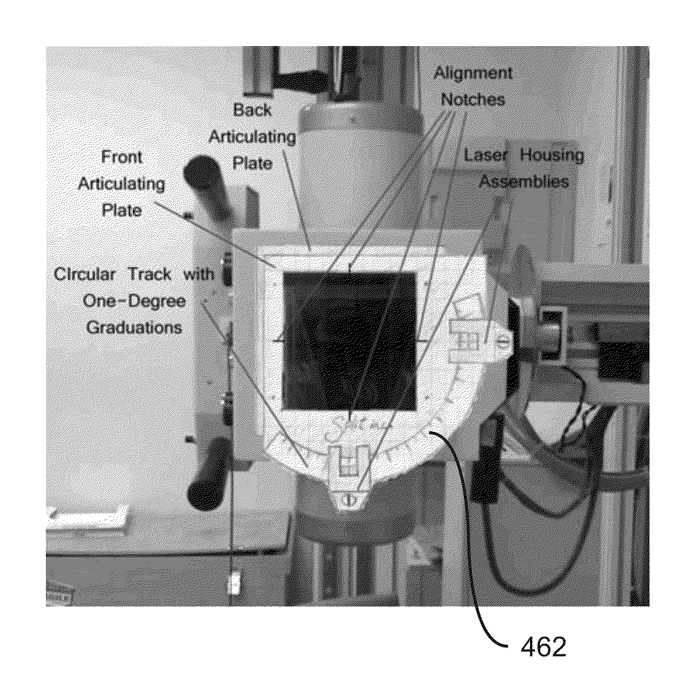
[0056]A Collimator Laser Unit 400 is mounted on the face of the collimator 300 as shown in FIGS. 3A and 3B. It is mounted on collimator 300 by an attachment mechanism comprising a system of horizontal and vertical tracks 410, 420 that allows it to be centered with respect to the x-ray beam. Two horizontal tracks 410 ...


PUM

PropertyMeasurementUnit
angleaaaaaaaaaa
angleaaaaaaaaaa
sizeaaaaaaaaaa

Abstract

A radiographic apparatus having a laser positioning system comprising three independent laser units for positioning a patient in three-dimension for the purpose of taking x-rays. Each laser unit is orthogonally oriented in respect to the others, such that the first laser unit projects a laser beam aligned with the x-ray beam in said first lateral direction, and the second laser unit projects a laser beam in a second lateral direction that is orthogonal to the first lateral direction, and the third laser unit projects a laser beam in a vertical direction that is orthogonal to both the first and second lateral directions. With the patient properly oriented by the laser system, x-ray films are taken that can be sequenced for radiographic animation analysis.

Description

FIELD OF THE INVENTION[0001]The present invention is directed to a system and method of taking radiographic images, commonly known as x-rays. More particularly, the invention is directed to a system and method of using lasers in three dimensions to position patients for x-rays that can be sequenced for radiographic animation analysis.BACKGROUND OF THE INVENTION[0002]1. Conventional X-Ray Apparatuses and Methods[0003]It is well known that the use of x-rays is vital in the treatment and diagnosis of patients, especially in chiropractic care. The effectiveness of radiographic diagnosis is critically dependent on the accuracy and quality of the x-ray images, which depend on the proper positioning the subject patient. The more precise the patient is aligned with the x-ray, the better is the resulting image. As such, the effectiveness of radiographic diagnosis is often compromised because it can be difficult to get the patient in just the right position and to orient the x-ray machine acc...

Claims


Application Information

Patent Timeline
Patent Type & Authority Applications(United States)
IPC IPC(8): A61B6/08G01N23/04
CPCA61B5/1128A61B6/505A61B6/08A61B5/70
Inventor VAZQUEZ, DAVID
Owner VAZQUEZ DAVID
Why Eureka
Try Eureka