
Test device and method for automatic pressure regulating valve of electronic braking system

a technology of electronic braking system and test device, which is applied in the direction of fluid loss/gain rate measurement, fluid tightness measurement, instruments, etc., can solve the problems of low efficiency, high risk, and not only time-consuming and laborious, so as to avoid the high risk of field testing, improve test efficiency, and ensure the effect of test consistency

Pending Publication Date: 2022-06-23
WUHAN UNIV OF TECH
View PDF0 Cites 7 Cited by
  • Summary
  • Abstract
  • Description
  • Claims
  • Application Information

AI Technical Summary

Benefits of technology

The present patent provides an efficient and safe test device and method for an automatic pressure regulating valve of an EBS system. The test device includes a special bracket, insulating operating desk, and frame to fix the valve and ensure the smoothness of the pneumatic circuit. The insulating operating desk includes an insulating pad and bench panel for electrical safety. The test method involves subjecting the valve to a bench test before being installed on a vehicle, and continuously modifying its parameters through tests to improve its performance and meet the real-time, fast, independent, and accurate regulation requirements of EBS of commercial vehicles. The test device and method meet the function and performance test requirements of automatic pressure regulating valves of EBS of commercial vehicles and promote the development of EBS technology of commercial vehicles.

Problems solved by technology

If a field test is directly adopted, it is not only time-consuming and labor-intensive, but also has low efficiency and high risk.

Method used


Image

  • Test device and method for automatic pressure regulating valve of electronic braking system
  • Test device and method for automatic pressure regulating valve of electronic braking system
  • Test device and method for automatic pressure regulating valve of electronic braking system

Examples


Embodiment Construction

[0043]The present disclosure is further described in detail below with reference to the accompanying drawings and specific embodiments.

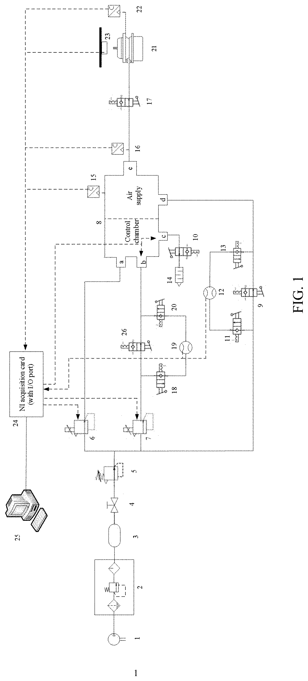
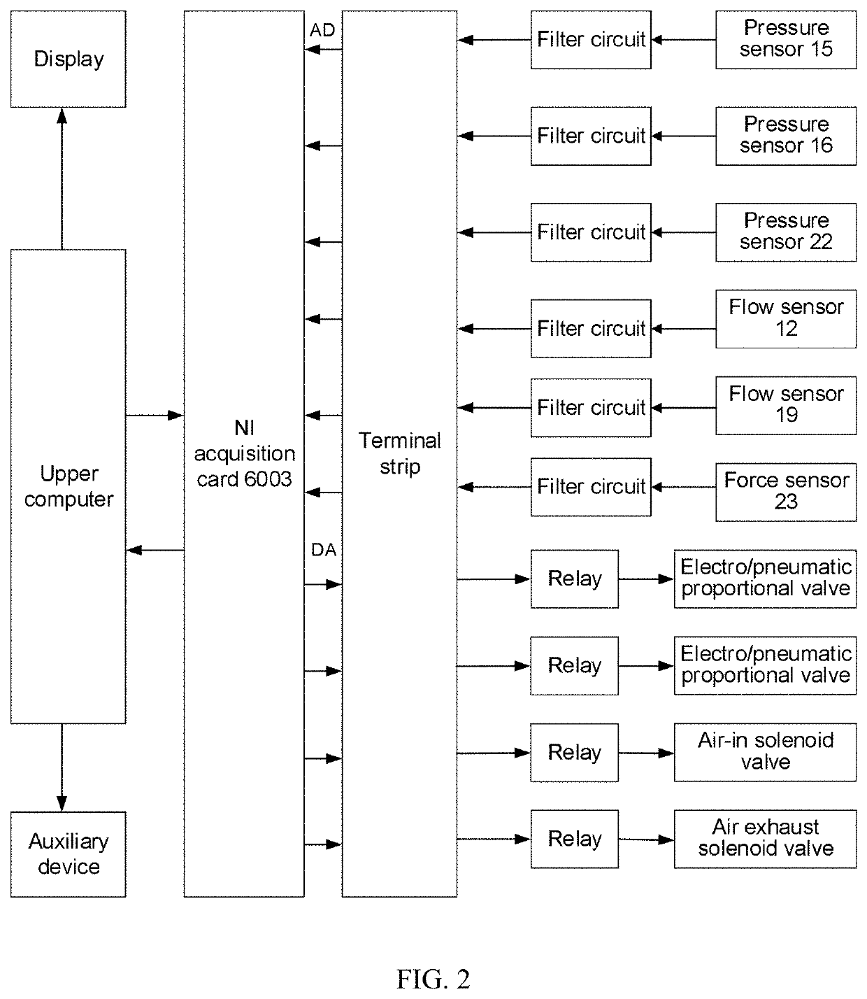
[0044]As shown in FIG. 1, a test device for an automatic pressure regulating valve of an EBS according to an embodiment of the present disclosure includes a test bench, an air supply 1, a pneumatic circuit, a brake chamber 21, a valve, a sensor, a silencer 14, a signal processing unit, and an industrial computer 25.

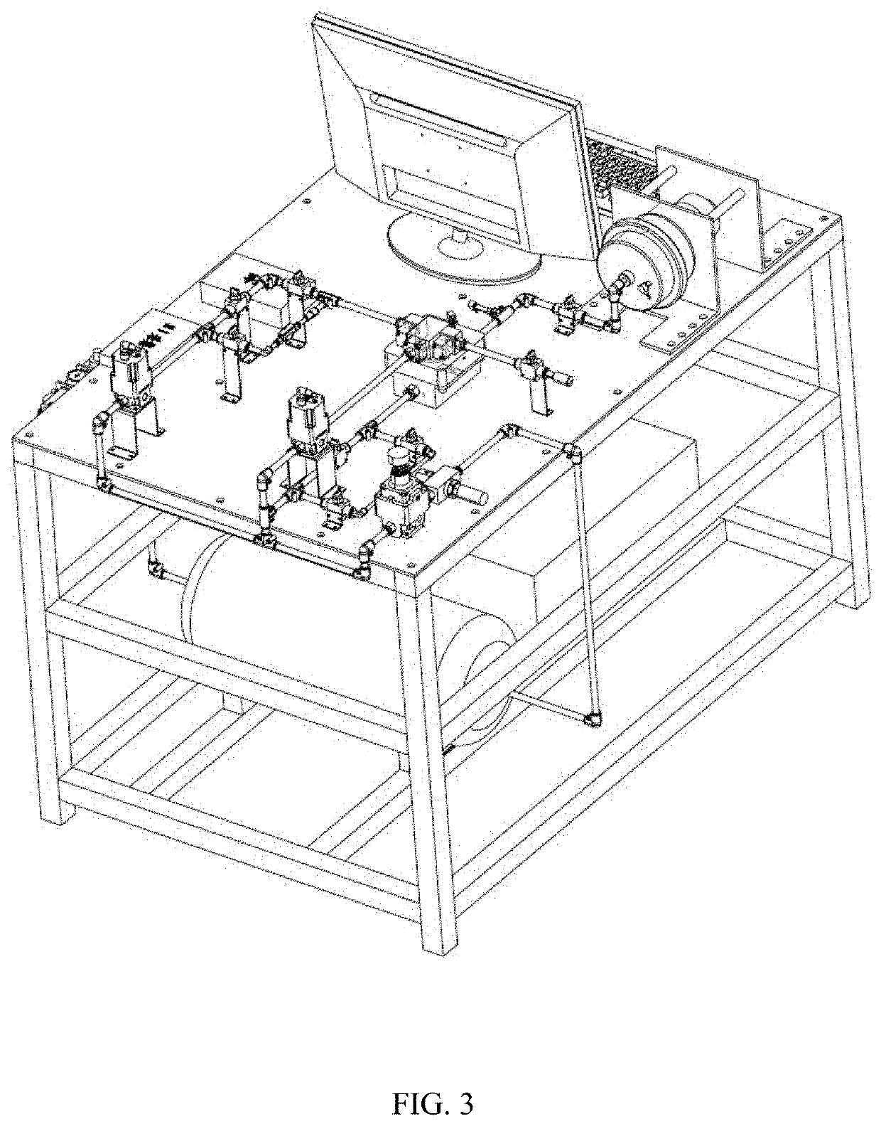
[0045]As shown in FIG. 3 to FIG. 5, the test bench includes a special bracket, an insulating operating desk, and a frame; the special bracket is made of 304 stainless steel, including an on-off valve bracket, a shut-off valve bracket, an electro / pneumatic proportional valve bracket, a brake chamber bracket, and a force sensor bracket, which are respectively configured to fix an on-off valve 4, a shut-off valve, an electro / pneumatic proportional valve, a brake chamber 21, and a force sensor 23 on an insulating operating desk through bolts, ...


PUM


Abstract

A test device for an automatic pressure regulating valve of an electronic braking system includes a test device composed of an air supply, a pneumatic circuit, a valve, a sensor, a signal processing unit, and a control unit. By subjecting an automatic pressure regulating valve to a bench test including a functional test, a static performance test, a dynamic performance test, an air tightness test, a leakage test, and a brake chamber braking force test, the present disclosure avoids the high risk of a field test, improves the test efficiency, and ensures the test consistency. An automatic pressure regulating valve is tested before being loaded on a vehicle, and parameters of the automatic pressure regulating valve are continuously modified through tests to improve the performance, such that the automatic pressure regulating valve can meet the real-time, fast, independent, and accurate regulation requirements of EBS of commercial vehicles.

Description

CROSS-REFERENCE TO RELATED APPLICATIONS[0001]This application is a continuation of International Patent Application No. PCT / CN2021 / 101823 with a filing date of Jun. 23, 2021, designating the United States, now pending, and further claims priority to Chinese Patent Application No. 202010588181.X with a filing date of Jun. 24, 2020. The content of the aforementioned applications, including any intervening amendments thereto, are incorporated herein by reference.TECHNICAL FIELD[0002]The present disclosure belongs to the technical field of motor vehicle braking, and in particular relates to a test device and method for an automatic pressure regulating valve of an electronic braking system (EBS).BACKGROUND ART[0003]The safety, stability, and smoothness of commercial vehicles are the focus of the road transportation industry. An air brake system is a core module that determines the braking performance of commercial vehicles and is one of the most important devices to avoid traffic acciden...

Claims


Application Information

Patent Timeline
Patent Type & Authority Applications(United States)
IPC IPC(8): G01M3/28
CPCG01M3/2876G01M13/003F17D5/00
Inventor LI, GANGYANBAO, HANWEIHU, JIANGU, ZHIQIANGYANG, FANG
Owner WUHAN UNIV OF TECH
Learn More