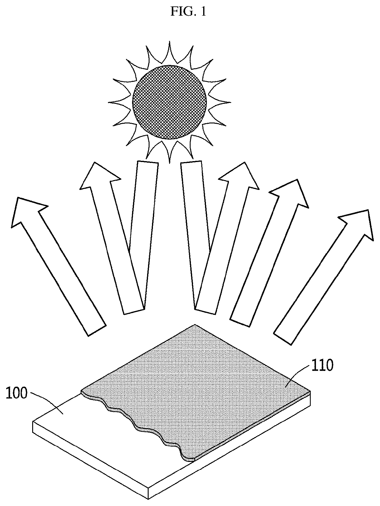
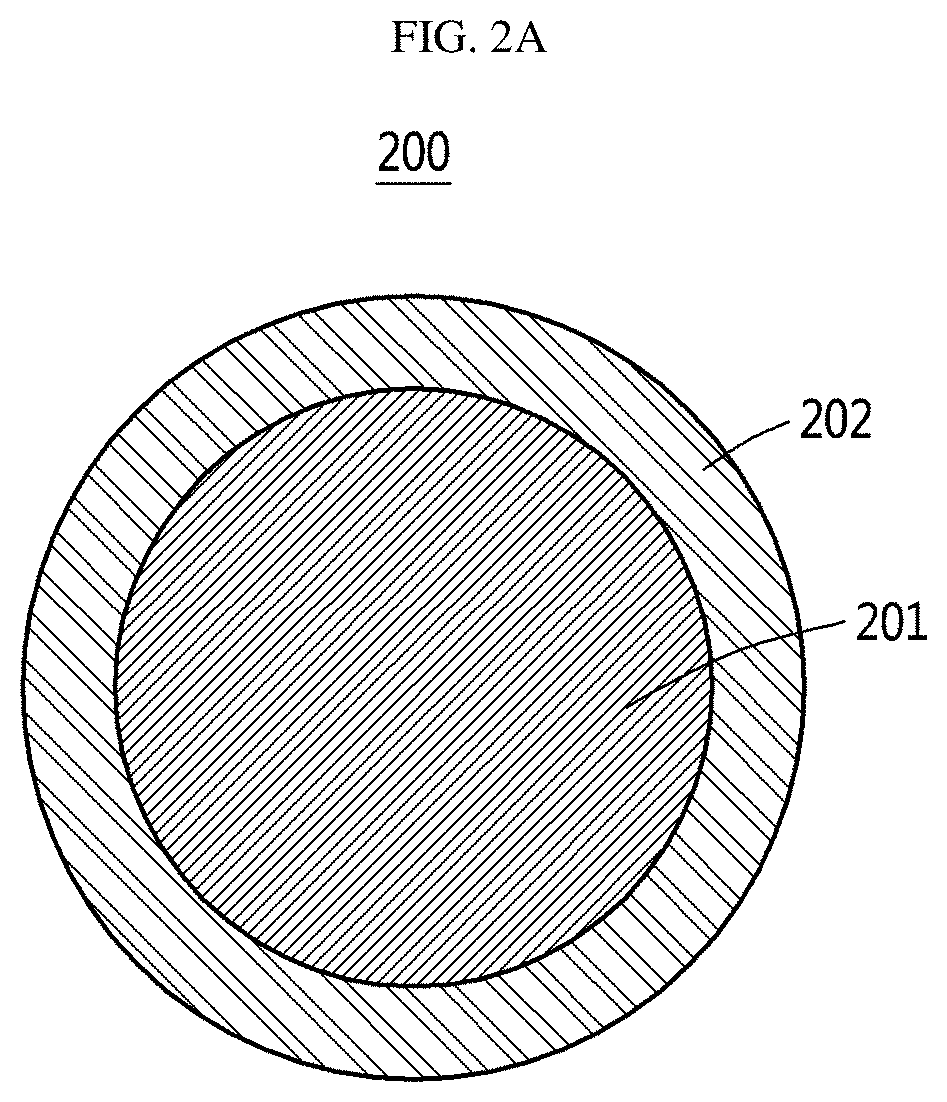
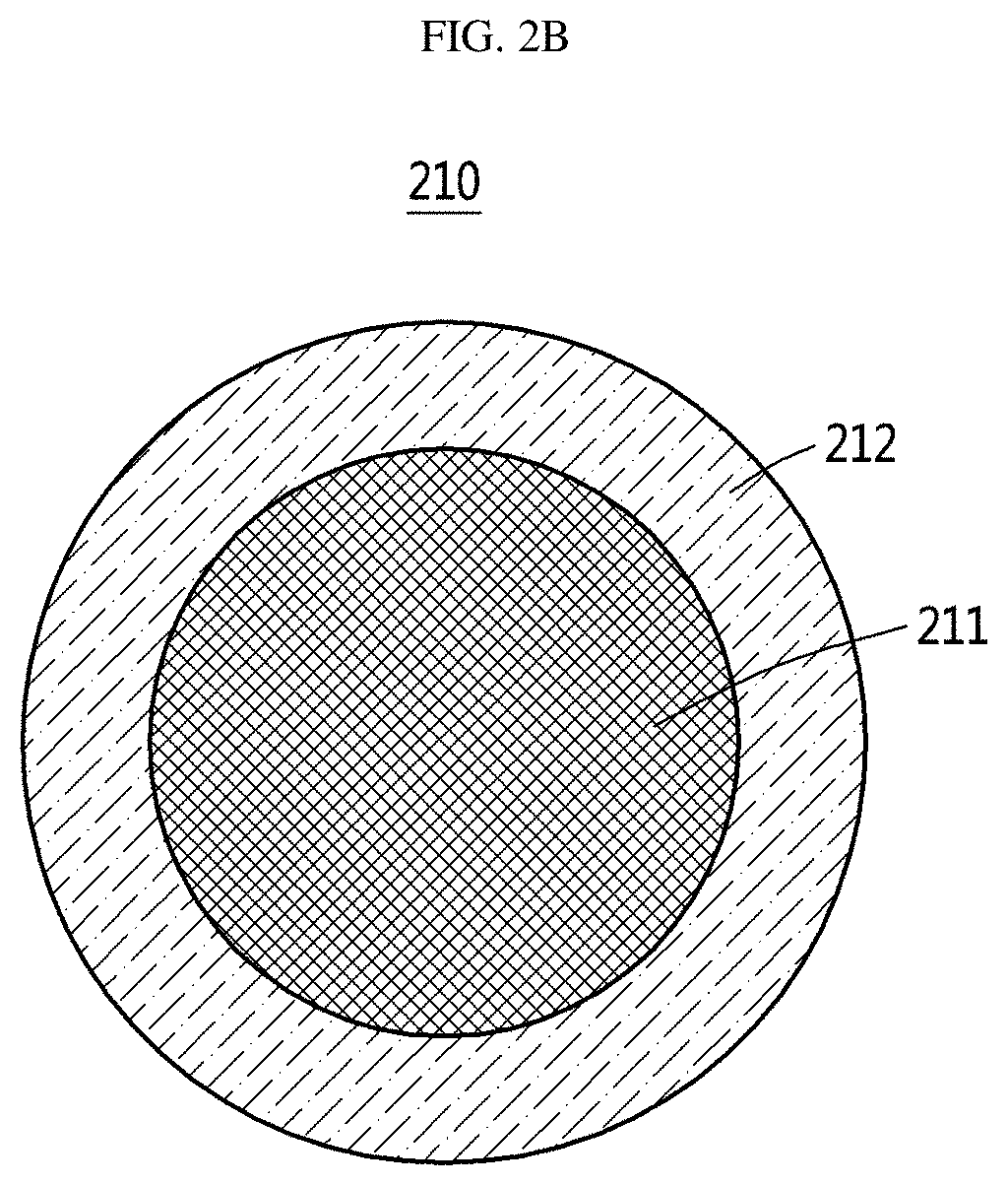
Radiative cooling device including paint coating layer composed of NANO or micro particles
- Summary
- Abstract
- Description
- Claims
- Application Information
AI Technical Summary
Benefits of technology
Problems solved by technology
Method used
Image

Examples
Embodiment Construction
[0066]Hereinafter, various embodiments of the present disclosure will be described with reference to the accompanying drawings.
[0067]The embodiments and terms used therein are not intended to limit the technology described in the present disclosure to a specific embodiment, and it should be understood to include various modifications, equivalents, and / or substitutes for the embodiment.
[0068]Hereinafter, in describing various embodiments, the detailed description of related known functions or constitutions will be omitted if it is determined that the functions or constitutions unnecessarily make the gist of the present invention unclear.
[0069]In addition, terms to be described below, as terms which are defined in consideration of functions in various embodiments, may vary depending on the intention of a user or an operator or usual practices. Accordingly, the terms need to be defined based on contents throughout this specification.
[0070]In connection with the description of the drawi...
PUM
| Property | Measurement | Unit |
|---|---|---|
| Thickness | aaaaa | aaaaa |
| Thickness | aaaaa | aaaaa |
| Angle | aaaaa | aaaaa |
Abstract
Description
Claims
Application Information
 - R&D
- Intellectual Property
- Life Sciences
- Materials
- Tech Scout
- Unparalleled Data Quality
- Higher Quality Content
- 60% Fewer Hallucinations
Browse by: Latest US Patents, China's latest patents, Technical Efficacy Thesaurus, Application Domain, Technology Topic, Popular Technical Reports.
© 2025 PatSnap. All rights reserved.Legal|Privacy policy|Modern Slavery Act Transparency Statement|Sitemap|About US| Contact US: help@patsnap.com