
Infrared-emitting compound, and luminescent thin film, luminescent particle, wavelength conversion film and infrared-emitting surface light source containing same

Pending Publication Date: 2022-05-05
KONICA MINOLTA INC
View PDF0 Cites 0 Cited by
  • Summary
  • Abstract
  • Description
  • Claims
  • Application Information

AI Technical Summary

Benefits of technology

The present invention relates to an infrared-emitting compound that can produce long-wavelength light with high luminescence quantum yield. By introducing a specific aromatic ring in the molecule, the t conjugate system may be extended while suppressing molecular vibration, resulting in high emission quantum yield and long-wavelength emission. This compound can be used to create luminescent thin films, particles, and wavelength conversion films with improved efficiency. Additionally, the present invention provides an infrared-emitting surface light source with a wavelength conversion film. The effect of the patent invention is to provide an infrared-emitting compound with improved luminescence quantum yield and long-wavelength light emission.

Problems solved by technology

However, compounds that emit infrared light generally have a problem in that the nonradiative deactivation is apt to occur because the energy difference between the excited state and the ground state is small, and the luminescence quantum yield is low as compared with a fluorescent material that emits visible light.

Method used

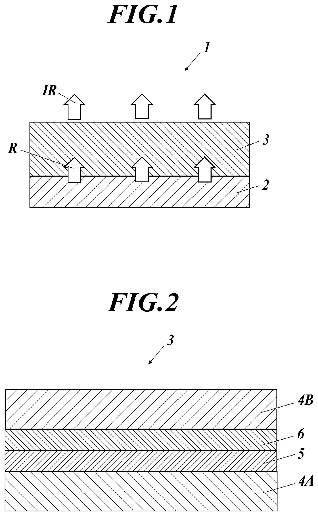

Image

  • Infrared-emitting compound, and luminescent thin film, luminescent particle, wavelength conversion film and infrared-emitting surface light source containing same
  • Infrared-emitting compound, and luminescent thin film, luminescent particle, wavelength conversion film and infrared-emitting surface light source containing same
  • Infrared-emitting compound, and luminescent thin film, luminescent particle, wavelength conversion film and infrared-emitting surface light source containing same

Examples


example 1

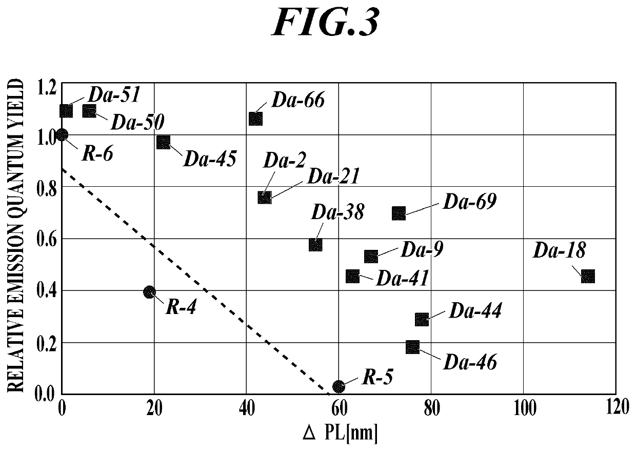
[0104]For each of the 13 infrared-emitting compounds of the present invention and the comparative compounds R4 to R-6 used in the following examples, the dihedral angle was calculated using a Gaussian 09 manufactured by Gaussian, Inc. as a software for calculating a molecular orbital under the conditions described above The results are indicated in Table I. In the case of a compound having no substituent according to the present invention, it was described as a hyphen “-”.

TABLE IDihedral angleCompound[degree]RemarksR-4—Comparative ExampleR-538.4Comparative ExampleR-638.4Comparative ExampleDa-2186.4Present ExampleDa-3890Present ExampleDa-286.4Present ExampleDa-4190Present ExampleDa-4458.8Present ExampleDa-4558.8Present ExampleDa-4655.1Present ExampleDa-955.1Present ExampleDa-5090.0Present ExampleDa-5186.4Present ExampleDa-1886.4Present ExampleDa-6686.4Present ExampleDa-6958.8Present Example

[0105]The emission wavelength and the emission quantum yield in the solution of each of the 13 ...

example 2

[0119]The luminescence quantum yield in the luminescent particles was measured for the infrared-emitting compound of the present invention and the comparative compound.

(1) Preparation of Luminescent Particles

[0120]To 96 μL of a polystyrene (PS) particle dispersion (solid content: 5.2% by mass, volume average particle diameter of polystyrene particles: 0.12 μm, dispersion medium: water) were added 100 μL of water, 50 μL of a 2% aqueous solution of a nonionic surfactant (Kolliphor P407, manufactured by Sigma-Aldrich Co., Ltd.), and 100 μL of a 0.01 mmol / L THF solution of each compound shown in Table IV to prepare a mixed liquid of polystyrene particles and each compound. Polystyrene particles were prepared by stirring the mixture at 25° C. for 2 minutes.

[0121]Using a dispersion of the obtained polystyrene particles, the particles were sedimented by a centrifugal purification method, and after removing the supernatant liquid, pure water was added to redisperse the particles. This opera...

example 3

[Preparation of Wavelength Conversion Film]

(Preparation of Wavelength Conversion Film 3)

[0124]The wavelength conversion film 3 having the structure shown in FIG. 2 was produced according to the following method.

[0125]To toluene as a solvent, polystyrene (manufactured by ACROS ORGANICS Co., Ltd., weight-average molecular weight Mw=260000) as a matrix material and an infrared-emitting compound Da-53 of the present invention were added so as to have a mass ratio of 99:1, and these were placed in a eggplant flask and heated and stirred at 80° C. thereby sufficiently dissolving the mixture.

[0126]Next, on the entire surface of one side of a polyethylene naphthalate film (manufactured by Teijin DuPont Corporation, hereinafter abbreviated as PEN), the obtained mixed solution was applied using an applicator onto a gas barrier film in which an inorganic gas barrier layer made of SiOx was formed to have a thickness of 500 nm by using an atmospheric pressure plasma-discharge treatment apparatus...


PUM


Abstract

An infrared-emitting compound has a structure represented by the following Formula (1a). In Formula (1a), Ar and ring A each independently represent an aryl ring, a heteroaryl ring or a fused ring thereof. Q-Ar represents an infrared-emitting residue. R1 represents a group in which a dihedral angle between Ar and ring A is 45 degree or more. And a thick line represents a single bond or a double bond.

Description

TECHNICAL FIELD[0001]The present invention relates to an infrared-emitting compound, and a luminescent thin film, luminescent particles, a wavelength conversion film, and an infrared-emitting surface light source containing the same compound. More particularly, the present invention relates to an infrared-emitting compound which enables long wavelength emission and high emission quantum yield.BACKGROUND[0002]In recent years, infrared-emitting materials have attracted considerable attention from the viewpoint of their use in infrared cameras, biometric imaging, biometric sensing, and infrared communication. For example, a pulse oximeter, which is one of biological sensing, uses infrared light to calculate oxygen saturation in blood (refer to Non-Patent Document 1). In addition, it has been studied as a sensitizer for organic solar cells (refer to Non-Patent Document 2). With the expansion of the application field of infrared light, the requirements are becoming stricter with respect ...

Claims


Application Information

Patent Timeline
IPC IPC(8): C09K11/06H01L33/50
CPCC09K11/06C09K2211/1081C09K2211/107H01L33/502H05B33/12G02B5/20C09B57/00H10K85/652C07C211/54
Inventor MIYATA, YASUOUEDA, NORIKOTATSUMI, HIROKINAKABAYASHI, RYO
Owner KONICA MINOLTA INC
Learn More