Welding shield with artificial intelligence-controlled display

a technology of artificial intelligence and display, applied in the field of welding shields, can solve the problems of increasing fatigue, difficulty in estimating the end of the soldering line, and the need for the welder to control the movement of the light filter using pressure, and achieve the effect of reducing the intensity of the welding ar

Pending Publication Date: 2022-04-28
MALOV ALEXEY VICTOROVICH
View PDF0 Cites 1 Cited by
  • Summary
  • Abstract
  • Description
  • Claims
  • Application Information

AI Technical Summary

Benefits of technology

[0009]In one aspect, there is provided a welder's shield with artificial intelligence including a frame for mounting on a user's head; a camera mounted on the frame and directed forward toward a welding zone, so as to obtain images of the welding zone as video data; a display on an inner side of the frame; an optical device to enable the user to see the display; a processor coupled to a memory; a battery providing power to the processor, the display and the camera; the processor receiving a video data from the camera; the processor running an artificial intelligence application to process the video data from the video camera; the processor displaying images on the display based on output of the artificial intelligence application; the artificial intelligence application receiving the video data and detecting a welding arc in the welding zone using a pattern recognition algorithm; and the artificial intelligence application modifying the video data to reduce an intensity of the welding arc in the images that are to be displayed on the display, without reducing an intensity of a remainder of objects in the images being displayed.

Problems solved by technology

In such case, for example, it is difficult to estimate when the end of the soldering line will be reached, what part of the soldering line is done.
Such a regime is unnatural for the eyes and leads to increased fatigue.
Another disadvantage is the need for the welder to control the movement of the light filter using the pressure in the mouth.

Method used


Image

  • Welding shield with artificial intelligence-controlled display
  • Welding shield with artificial intelligence-controlled display
  • Welding shield with artificial intelligence-controlled display

Examples


Embodiment Construction

[0018]Reference will now be made in detail to the preferred embodiments of the present invention, examples of which are illustrated in the accompanying drawings.

[0019]The technical result is an improvement in working conditions, an increase in work productivity.

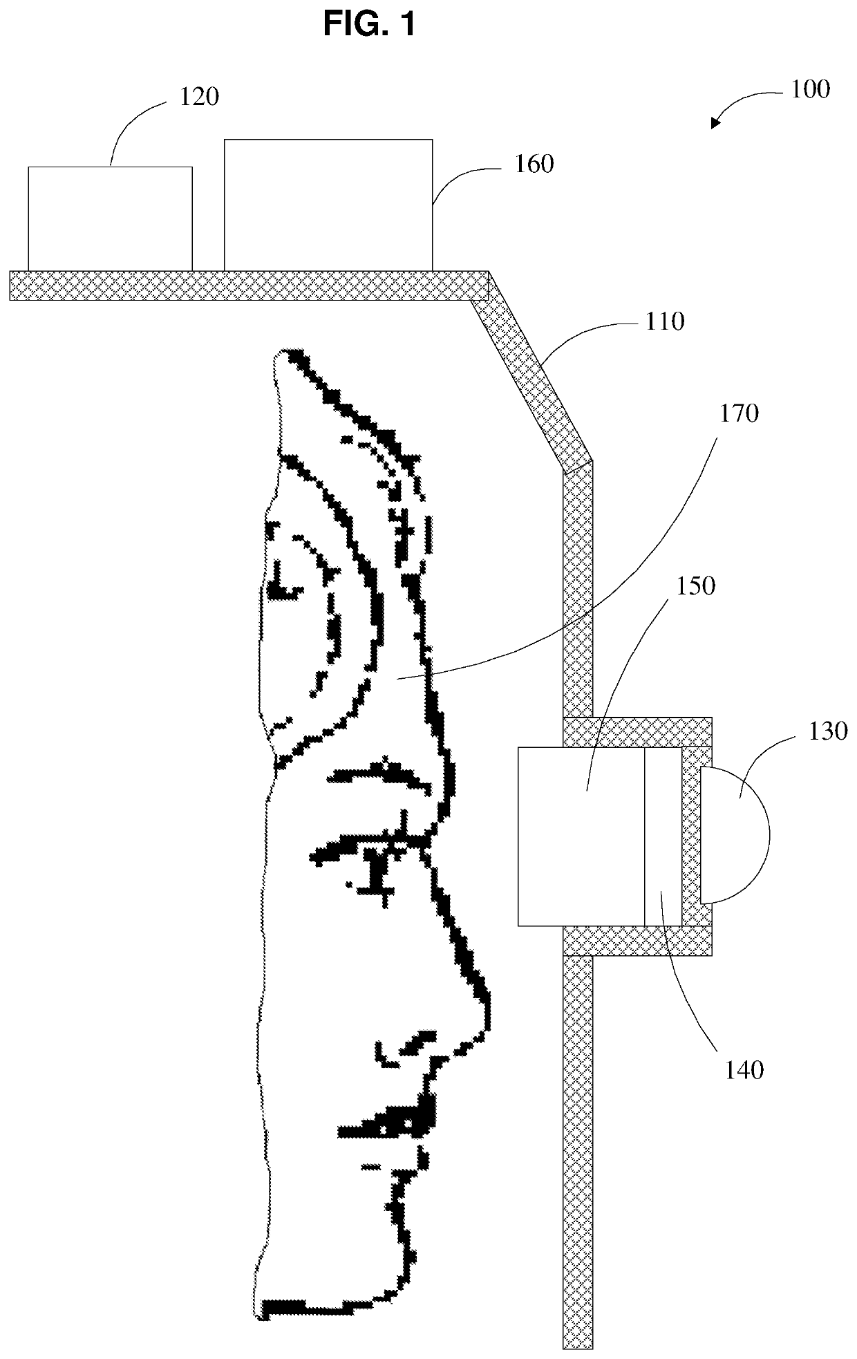
[0020]The task is solved as follows. The welding shield is a head-mounted device comprising:

[0021](1) autonomous power source, for example, an accumulator battery

[0022](2) One or several digital video cameras on the outer side of the shield. Above-mentioned digital video cameras directed in the direction of the welder's direct gaze, allowing to obtain an image with an angle of coverage of at least a direct view of the welder. Digital video cameras above designed for stable operation in the presence of bright light sources.

[0023](3) display on the inside side of the shield

[0024](4) an optical system located in front of the display and allowing the welder to adjust the image to the individual characteristics of the welder's vis...


PUM

PropertyMeasurementUnit
poweraaaaaaaaaa
photosensitivityaaaaaaaaaa
brightnessaaaaaaaaaa

Abstract

Welder's shield with AI includes a frame for mounting on a user's head; a camera mounted on the frame and directed forward toward welding zone, to obtain images of welding zone as video data; a display on an inner side of the frame; an optical device to enable the user to see the display; battery; processor receiving a video data from the camera; the processor running an AI application to process the video data; the processor displaying images on the display based on output of the AI application; the artificial intelligence application receiving the video data and detecting a welding arc in the welding zone using a pattern recognition algorithm; and the AI application modifying the video data to reduce an intensity of the welding arc in the images that are to be displayed on the display, without reducing an intensity of the rest of the images.

Description

CROSS REFERENCE TO RELATED APPLICATIONS[0001]This application claims priority to Russian Patent Application No. 2020134919, filed on Oct. 24, 2020, incorporated herein by reference.TECHNICAL FIELD[0002]The present disclosure relates to the field of welding production and can be used to protect a person during welding. More specifically, the present disclosure relates to personal protective equipment that has artificial intelligence.BACKGROUND OF THE RELATED ART[0003]A curved auto-darkening light filter (RU patent No. 2719306, priority dated Dec. 13, 2012) is known. The light filter changes its state from light-transmitting to shade mode under the influence of incident light. The auto-darkening light filter is manufactured by a method based on forming a liquid crystal cell. The invention provides a reduction in weight and an expansion of the field of view for the user.[0004]The disadvantages of welding shields based on this device, as well as other well-known commercial welding shiel...

Claims


Application Information

Patent Timeline
Patent Type & Authority Applications(United States)
IPC IPC(8): A61F9/06B23K9/095B23K9/32G02B27/01H04N5/58G06K9/00G06N3/08
CPCA61F9/06B23K9/0956B23K9/0953B23K9/322G02B27/0101G02B2027/0138G02B27/0176H04N5/58G06K9/00744G06N3/08G02B27/0172G06V20/20G06V10/82G02B2027/014G02B2027/0141B23K31/006G06N3/045F16P1/06G06V20/46
Inventor MALOV, ALEXEY VICTOROVICH
Owner MALOV ALEXEY VICTOROVICH
Why Eureka
Try Eureka