Probe for implantation into nervous tissue comprising a microelectrode or a set of microelectrodes

a technology of nervous tissue and probe, which is applied in the field of probes, can solve the problems of persistent local inflammation, tissue injury, affecting the active, non-insulated portion of the implanted microelectrode, etc., and achieve the effect of avoiding or avoiding

Pending Publication Date: 2022-04-14
NEURONANO AB
View PDF0 Cites 0 Cited by
  • Summary
  • Abstract
  • Description
  • Claims
  • Application Information

AI Technical Summary

Benefits of technology

[0005]An object of the invention is to provide a microelectrode implanted in soft tissue, in particular nervous or endocrine tissue, and electrically connected with control apparatus disposed exteriorly of the tissue, which avoids or at least reduces tissue irritation by movements of tissue abutting it or abutting a lead electrically connecting it with electrode control apparatus disposed outside the tissue of implantation.
[0006]Another object of the invention is to prevent or reduce dislocations of an implanted microelectrode by forces affecting the lead by which it is electrically connected with electrode control apparatus.
[0007]Still another object of the invention is to provide for increased freedom of lateral movement of an implanted microelectrode.

Problems solved by technology

These movements of tissues relative to each other result in shear forces at their bordering area, which risk causing persistent local inflammation and tissue injury.
In addition, shear forces of this kind may affect the position of the active, non-insulated portion of an implanted microelectrode.

Method used


Image

  • Probe for implantation into nervous tissue comprising a microelectrode or a set of microelectrodes
  • Probe for implantation into nervous tissue comprising a microelectrode or a set of microelectrodes
  • Probe for implantation into nervous tissue comprising a microelectrode or a set of microelectrodes

Examples


example 1

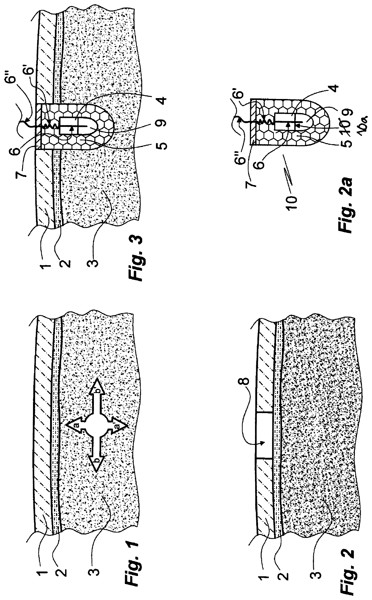
[0068]Implantation and tissue environment principles. FIGS. 1, 2, 2a and 3 illustrate schematically the implantation of a microelectrode probe into neural tissue. The neural tissue 3 here is brain tissue, protected by the skull bone 1 from which it is separated by a thin layer 2 comprising several sub-layers, such as the dura mater, the arachnoid mater, the pia mater and cerebrospinal fluid. The neural tissue 3 is prone to displacement in respect of the skull bone 1 by movements of the head, the displacement in a direction parallel with the skull bone 1 (arrows b, b′) generally being higher than in a perpendicular direction (arrows a, a′). Tissues intermediate between the skull bone 1 and brain tissue 3 are similarly displaced but not necessarily to the same extent.

[0069]Prior to implantation of a device according to the invention access to a desired position of the brain is provided by drilling a circular hole 8 in the skull (FIG. 2).

[0070]In the next step a device of the invention...

example 2

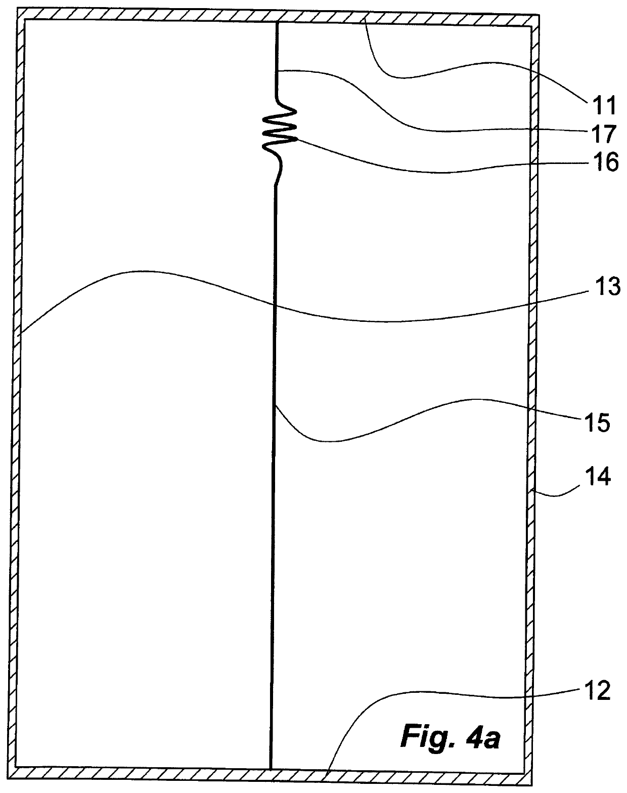
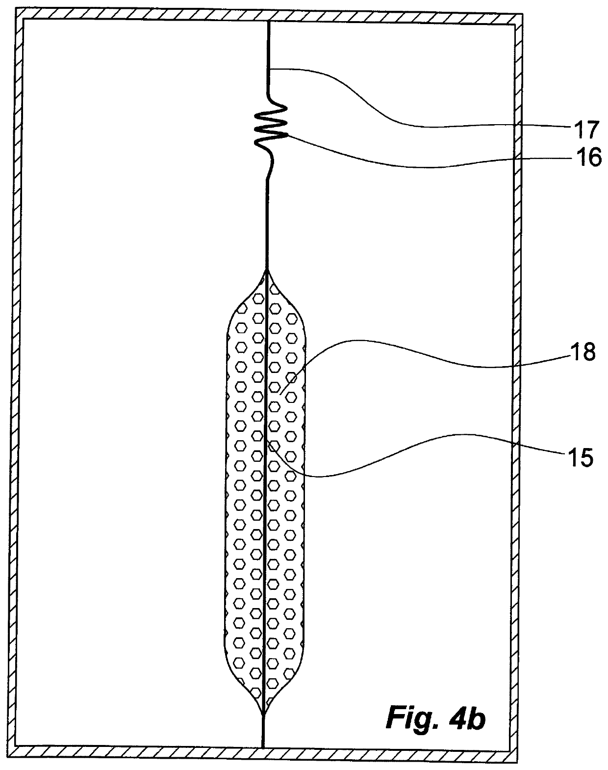
[0071]Manufacture of a microelectrode of the invention. For an understanding of the structure of a microelectrode probe of the invention and a microelectrode formed from it upon implantation the description of a process of its manufacture is helpful. Such a process is illustrated in FIGS. 4a through 4h or 4j.

[0072]At start (FIG. 4a) the ends of a metallic wire 15, 16, 17 are fastened at opposite sides 11, 12 of a rectangular frame 11, 12, 13, 14. The wire 15, 16, 17 comprises long and short straight terminal sections 15, 17 and a pre-bent intermediate coiled, zig-zag or meandered extendable section 16. Typically, the wire 15, 16, 17 has thickness of a few μm, such as from 1 μm to 20 μm, in particular from 2 μm to 12 μm. The wire 15, 16, 17 can be a single piece or comprise two or more sections of different compositions, such as of a first section 15 of platinum or iridium and a second section of 16, 17 of gold. Instead of a single wire 15, 16, 17 a bundle of ultra-thin wires of met...

example 3

[0089]FIG. 6a illustrates, in a simplified manner and in a perspective view, a microelectrode probe 40 of the invention comprising a distal chamber 46, 52 with cylindric 46 and hemispheric 52 sections, and a proximal chamber 47 of cylindrical form. The chambers 46, 52; 47 are separated by a radially extending wall 43. The microelectrode probe 40 is substantially rotationally symmetric in respect of a central axis C-C extending in a proximal / distal direction. The walls 44, 50; 45 (FIG. 6b), respectively, of the chambers 46, 52; 47 and the separating wall 43 are of a flexible polymer material, such as a Parylene C. The chambers 46, 52; 47 are filled with one or more of biocompatible carbohydrate material and biocompatible proteinaceous material, such as glucose and gelatin; for instance, the proximal chamber 47 and the cylindric portion 46 of the distal chamber 46, 52 are filled with carbohydrate material while the hemispheric portion 52 of the distal chamber 46, 52 is filled with gel...


PUM


Abstract

A microelectrode probe for implantation into soft tissue comprises an envelope of flexible polymer material divided by a wall into a distal and a proximal compartment filled with matrices of biocompatible material dissolvable or degradable in aqueous body fluid and comprising a centrally disposed electrically conducting core penetrating the wall and attached to it. The core is insulated at its proximal portion from which it extends to a holder for attachment to a tissue different from said soft tissue. The envelope and the core extending distally from the holder are embedded in an additional matrix of similar kind. Also disclosed is method for its manufacture, an array comprising two or more microelectrode probes and a microelectrode probe for incorporation into the array as well as method for the manufacture of the array.

Description

FIELD OF THE INVENTION[0001]The present invention relates to probes comprising single microelectrodes or sets of microelectrodes for implantation by insertion into soft tissue, in particular nervous tissue or endocrine tissue. The present invention furthermore relates to the use and manufacture of such probes.BACKGROUND[0002]Implantable microelectrodes and sets of microelectrodes have a wide scope of applications in medicine and veterinary medicine.[0003]A microelectrode implanted into nervous tissue, independent from whether constituting a single implant or pertaining to an implant comprising multiple microelectrodes such as a bundle or array of microelectrodes, requires electrical connection to control device(s) disposed exteriorly of the tissue. This connection is generally provided by thin insulated flexible electrical leads. The leads bridge tissues of various kind and stiffness and thereby become affected by their recurrent displacement relative to each other caused by breathi...

Claims


Application Information

Patent Timeline
Patent Type & Authority Applications(United States)
IPC IPC(8): A61B5/263A61B5/00
CPCA61B5/263A61B2562/028A61B5/6867A61B2562/125A61N1/0529A61N1/0536A61N1/0539A61N1/0558A61B5/24
Inventor SCHOUENBORG, JENS
Owner NEURONANO AB
Why Eureka
Try Eureka