
UV irradiation apparatus

a technology of irradiation apparatus and irradiation tube, which is applied in the direction of electrical apparatus, electric discharge lamp details, electric discharge lamp, etc., can solve the problems of poor startability and difficult turning of excimer lamps, and achieve the effect of improving startability and increasing irradiance maintenance rate, reducing power supply system, and high startability

Active Publication Date: 2022-02-24
USHIO DENKI KK
View PDF4 Cites 0 Cited by
  • Summary
  • Abstract
  • Description
  • Claims
  • Application Information

AI Technical Summary

Benefits of technology

The technical effect of this patent is to improve the ability of a UV irradiation apparatus that uses excimer lamps to start and operate.

Problems solved by technology

However, some excimer lamps have poor startability, and some of them are difficult to turn on after a long turn-off period.

Method used


Image

  • UV irradiation apparatus
  • UV irradiation apparatus
  • UV irradiation apparatus

Examples


Embodiment Construction

[0056]An embodiment of a UV irradiation apparatus according to the present invention will be described regarding the drawings. It is to be noted that all the following drawings are schematically shown, and the dimensional ratios of the drawings are not necessarily consistent with actual dimensional ratios. Further, the dimensional ratios of the drawings are not necessarily consistent with each other.

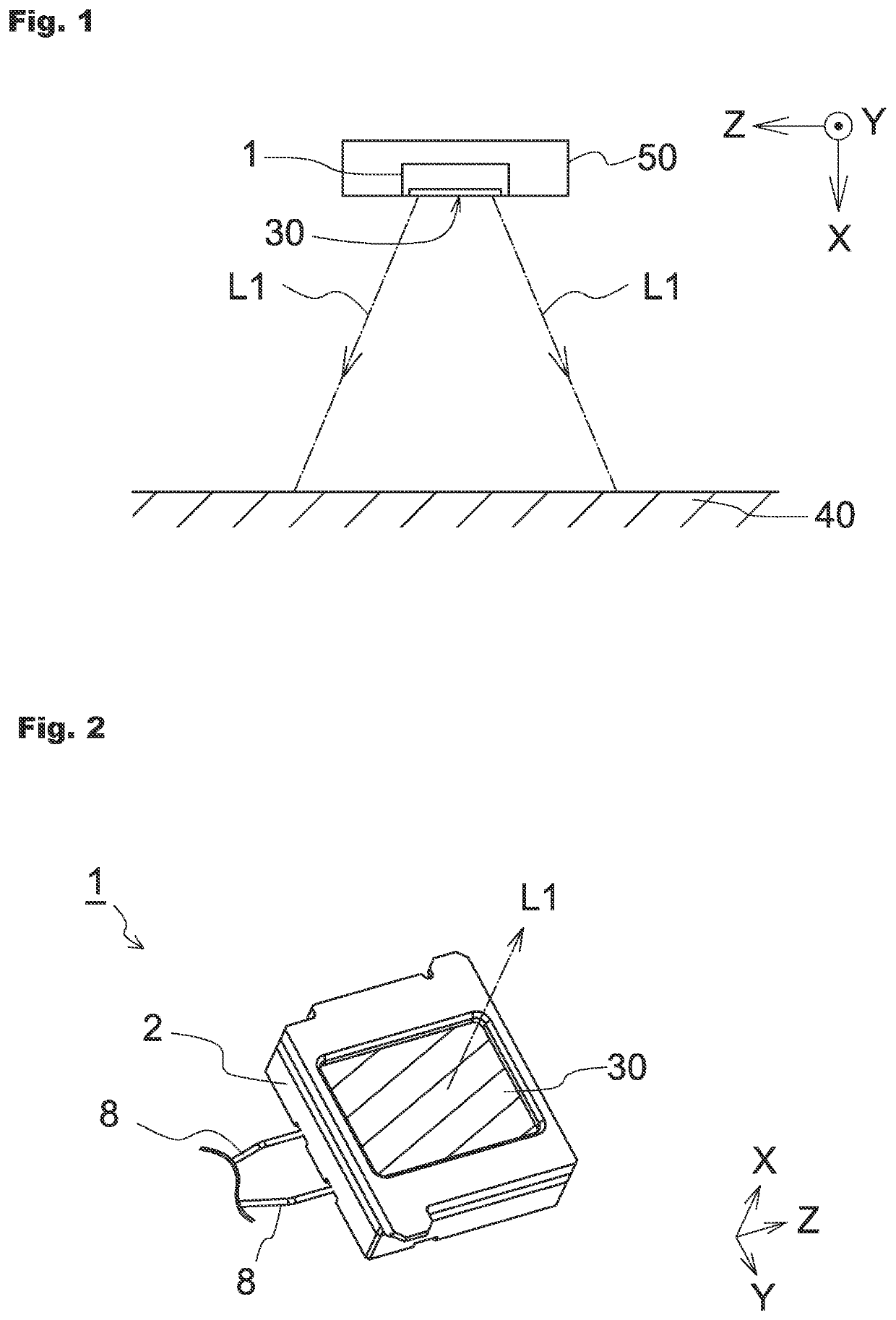
[0057]FIG. 1 is a diagram schematically showing one mode of use of the UV irradiation apparatus according to the present invention. FIG. 1 schematically shows how an area 40 to be irradiated is irradiated with ultraviolet light L1 emitted through a light extraction face 30 of a UV irradiation apparatus 1 installed in a housing 50.

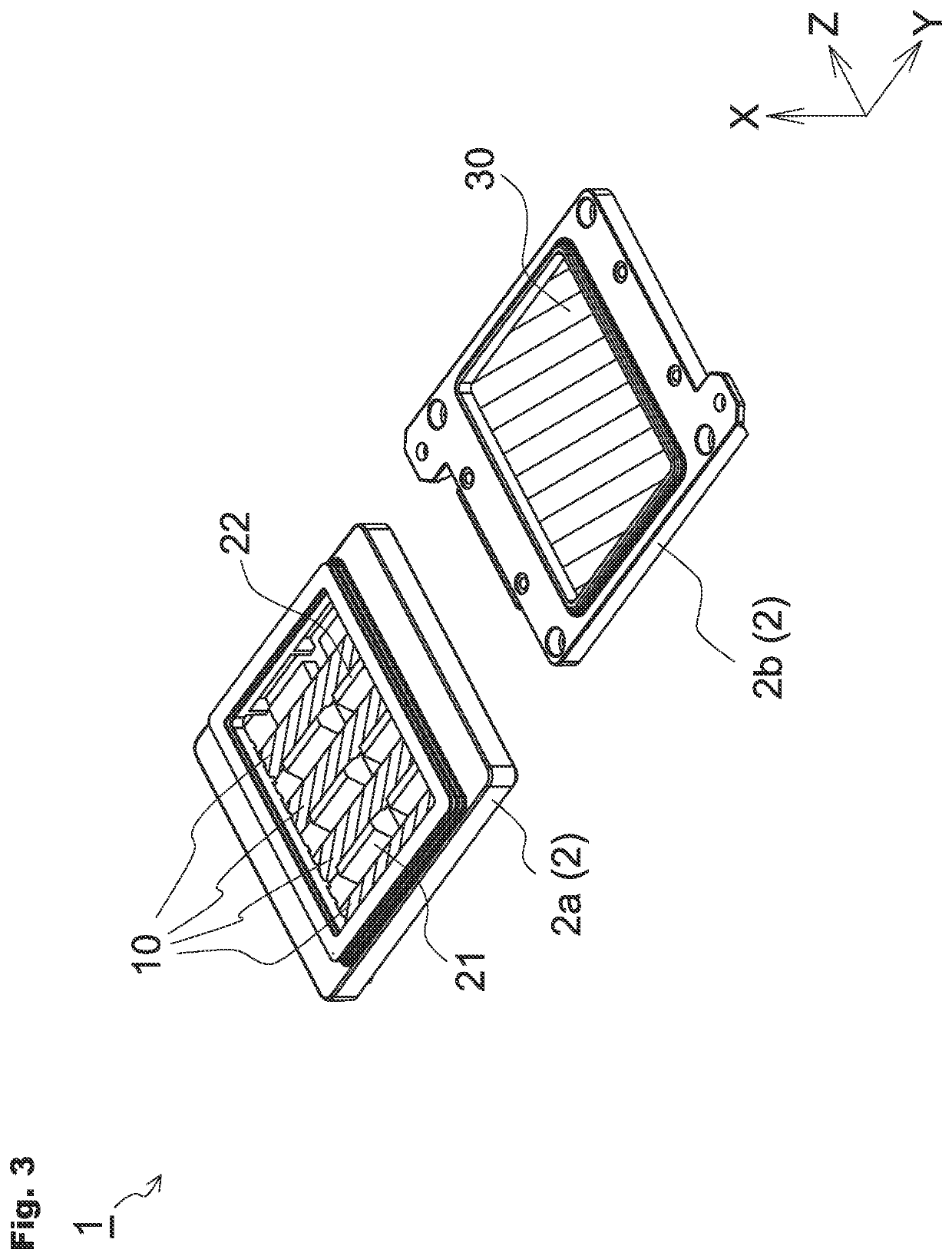
[0058]FIG. 2 is a perspective view schematically showing an example of the appearance of the UV irradiation apparatus 1. FIG. 3 is an exploded perspective view of FIG. 2, in which a casing 2 of the UV irradiation apparatus 1 is separated into a main body 2a and ...


PUM

PropertyMeasurementUnit
peak wavelengthsaaaaaaaaaa
peak wavelengthaaaaaaaaaa
wavelength bandaaaaaaaaaa

Abstract

To improve startability in a UV irradiation apparatus equipped with excimer lamps. The UV irradiation apparatus includes a plurality of excimer lamps each having a light-emitting tube filled with a discharge gas containing a noble gas. The plurality of excimer lamps includes a first excimer lamp filled with the discharge gas at a first enclosed gas pressure and a second excimer lamp filled with the discharge gas at a second enclosed gas pressure lower than the first enclosed gas pressure. The first excimer lamp is placed in a position such that at least part of light emitted from the second excimer lamp is allowed to enter the first excimer lamp.

Description

BACKGROUND OF THE INVENTIONField of the Invention[0001]The present invention relates to a UV irradiation apparatus and particularly relates to a UV irradiation apparatus equipped with excimer lamps.Description of the Related Art[0002]A lamp utilizing dielectric-barrier discharge hereinafter referred to as an “excimer lamp”) is conventionally known which is allowed to emit light by applying a voltage to a discharge gas enclosed within its light-emitting tube through a dielectric material such as quartz glass.[0003]Such an excimer lamp has a specific emission wavelength depending on the type of discharge gas or the combination of discharge gases. For example, excimer lamps are known which use, as a discharge gas, a noble gas such as argon (Ar), krypton (Kr), or xenon (Xe) or a mixed gas of the noble gas and a halogen gas such as fluorine (F), chlorine (CO, iodine (I), or bromine (Br). For example, Patent Document 1 listed below states that various lights whose peak wavelengths belong ...

Claims


Application Information

Patent Timeline
Patent Type & Authority Applications(United States)
IPC IPC(8): H01J61/16H01J61/06H01J65/04
CPCH01J61/16A61L2/10H01J65/046H01J61/06H01J61/02H01J61/54H01J61/125
Inventor YAGYU, HIDEAKI
Owner USHIO DENKI KK
Learn More