Exhaust treatment system and method

Inactive Publication Date: 2022-01-27
SHANGHAI BIXIUFU ENTERPRISE MANAGEMENT CO LTD
View PDF0 Cites 0 Cited by
  • Summary
  • Abstract
  • Description
  • Claims
  • Application Information

AI Technical Summary

Benefits of technology

The present invention aims to provide an exhaust treatment system and method with better exhaust purification treatment effect. The invention solves the problem of liquid water in the exhaust and improves the ionization dedusting effect. The invention also addresses the issue of high temperature impacts and ensures efficient dust collecting capability. The invention includes a water removing device, a feature to reduce electric field coupling, and a reaction field with an ozone entrance. The invention also utilizes an electric field back corona discharge phenomenon and restricts injection current to complete the carbon black cleaning treatment. The invention also selects parameters to reduce the coupling time of the electric field.

Problems solved by technology

The exhaust formed by combustion usually contains a large amount of pollution, which will cause serious contamination to the environment when the exhaust is discharged directly into the atmosphere.
(1) Regeneration is needed when a DPF captures a certain amount of particulates. Otherwise, the engine exhaust backpressure will rise and the working state will deteriorate, seriously affecting performance and oil consumption and even blocking the DPF, which can cause engine failure. Thus, a DPF needs to be maintained regularly, and a catalyst needs to be added to it. Even with regular maintenance, the accumulation of particulates restricts an exhaust flow. As a result, the backpressure is increased, affecting the performance and fuel consumption of the engine.
(2) The dedusting effect of a DPF is unstable and fails to meet the latest filtering requirements of engine intake treatment.
In the prior art, there exist problems including large space requirements, a complex system structure, and a poor dedusting effect,

Method used


Image

  • Exhaust treatment system and method
  • Exhaust treatment system and method
  • Exhaust treatment system and method

Examples


embodiment 1

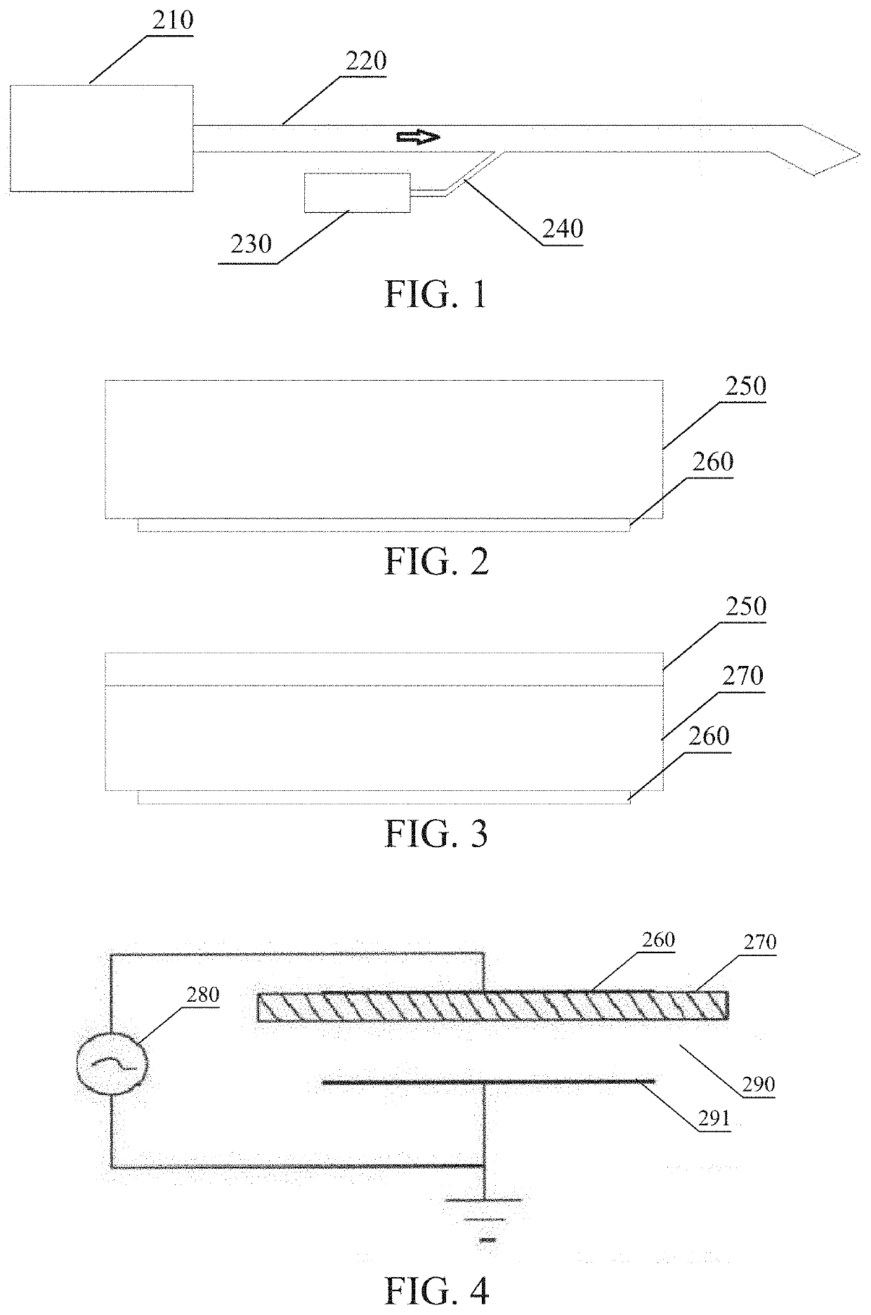
[0744]As shown in FIG. 5, an exhaust dedusting system includes a water removing device 207 and an electric field device. The electric field device includes a dedusting electric field anode 10211 and a dedusting electric field cathode 10212. The dedusting electric field anode 10211 and the dedusting electric field cathode 10212 are used to generate an ionization dedusting electric field. The water removing device 207 is used to remove liquid water before an electric field device entrance. When the exhaust has a temperature of lower than 100° C., the water removing device 207 removes liquid water in the exhaust. The water removing device 207 is an electrocoagulation device. The arrow in the figure shows the flow direction of exhaust.

[0745]An exhaust dedusting method includes the following steps. When the exhaust has a temperature of lower than 100° C., liquid water in the exhaust is removed, and then ionization dedusting is performed, wherein the liquid water in the exhaust is removed...

embodiment 2

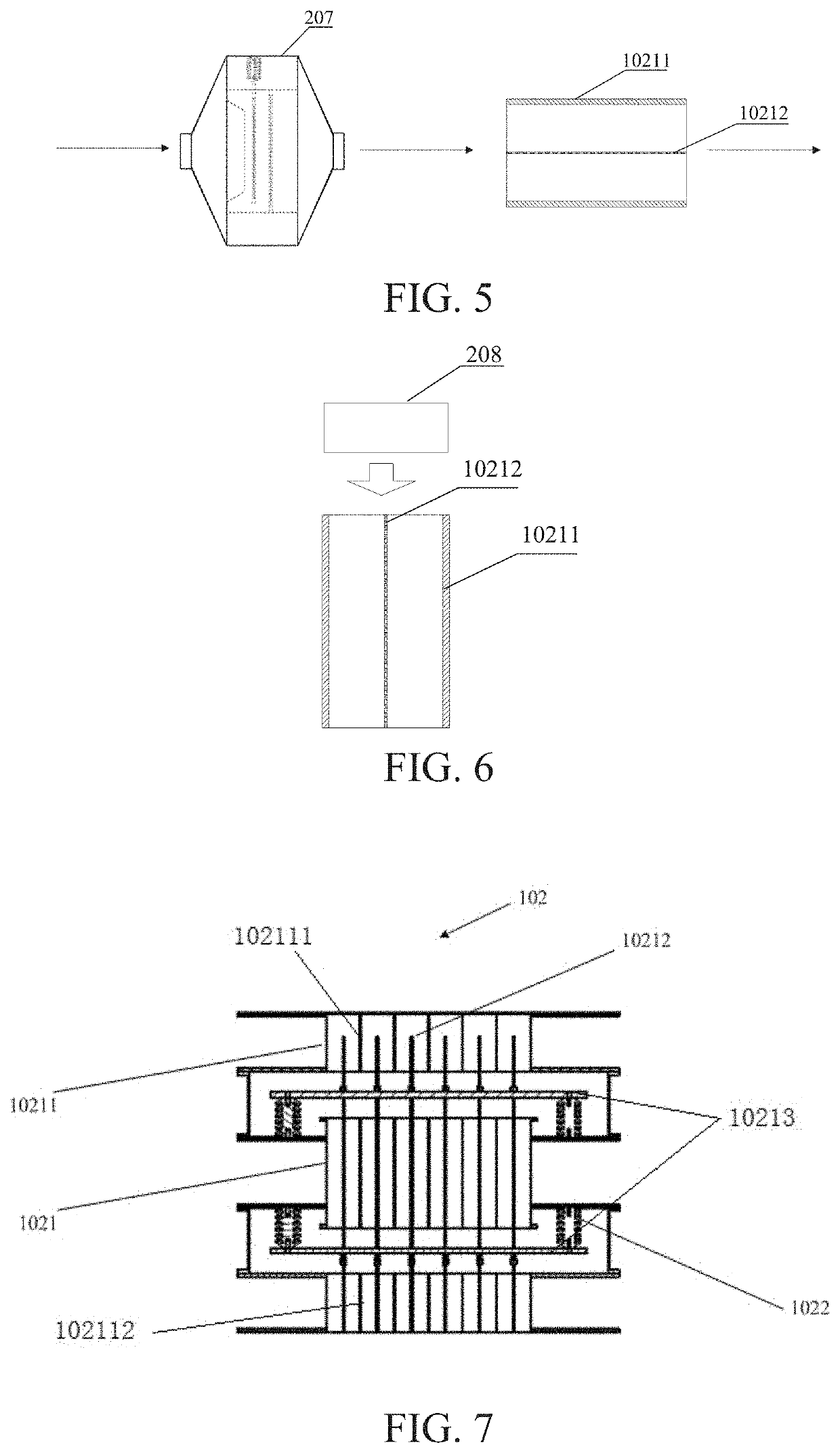
[0746]As shown in FIG. 6, an exhaust dedusting system includes an oxygen supplementing device 208 and an electric field device. The electric field device includes a dedusting electric field anode 10211 and a dedusting electric field cathode 10212. The dedusting electric field anode 10211 and the dedusting electric field cathode 10212 are used to generate an ionization dedusting electric field. The oxygen supplementing device 208 is used to add an oxygen-containing gas before the ionization dedusting electric field. The oxygen supplementing device 208 adds oxygen by introducing external air, with the amount of supplemented oxygen depending upon the content of particles in the exhaust. The arrow in the figure shows the flow direction of the oxygen-containing gas added by the oxygen supplementing device.

[0747]An exhaust dedusting method includes a step of adding an oxygen-containing gas before an ionization dedusting electric field to perform ionization dedusting, wherein the oxygen is...

embodiment 3

[0749]An exhaust emission equipment-based gas treatment system of the present embodiment further includes an exhaust treatment device which is configured to treat an exhaust to be emitted into the atmosphere.

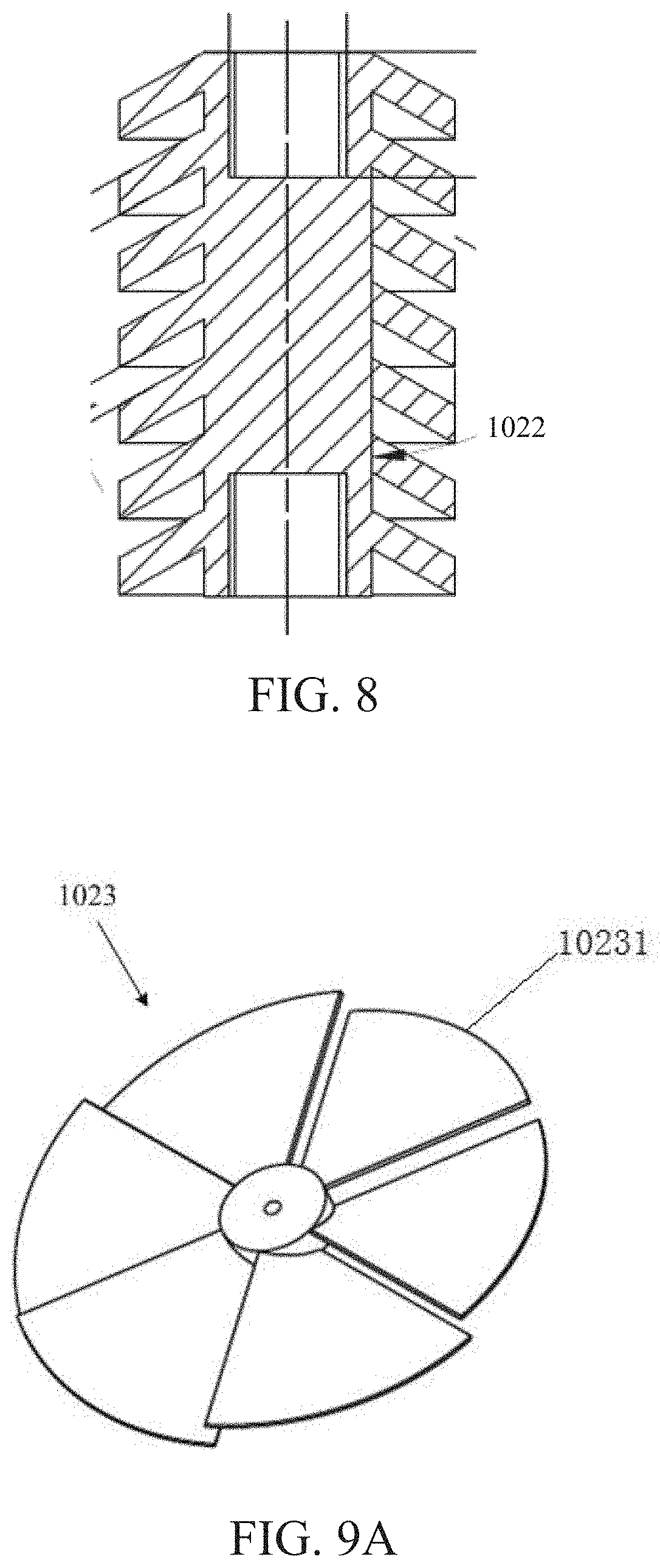
[0750]FIG. 7 shows a structural schematic diagram of an embodiment of an exhaust treatment device. As shown in FIG. 7, the exhaust treatment device 102 includes an electric field device 1021, an insulation mechanism 1022, an equalizing device, an exhaust water filtering mechanism, and an exhaust ozone mechanism.

[0751]The exhaust water filtering mechanism in the present invention is optional. Namely, the exhaust dedusting system provided in the present invention may include the exhaust water filtering mechanism, or the exhaust water filtering mechanism may be omitted.

[0752]The electric field device 1021 includes a dedusting electric field anode 10211 and a dedusting electric field cathode 10212 provided inside the dedusting electric field anode 10211. An asymmetric electrostatic ...


PUM


Abstract

An exhaust treatment system includes an exhaust dust removal system and an exhaust ozone purification system. The exhaust dust removal system has a dust removal system inlet, a dust removal system outlet, and an electric field device (1021). The exhaust ozone purification system includes a reaction field (202) for mixing an ozone stream with an exhaust stream for a reaction. The exhaust treatment system is able to effectively remove particulate matters from the exhaust, improving the purifying treatment effect on the exhaust.

Description

TECHNICAL FIELD[0001]The present invention belongs to the field of environmental protection, and it relates to an exhaust treatment system and method.BACKGROUND ART[0002]The exhaust formed by combustion usually contains a large amount of pollution, which will cause serious contamination to the environment when the exhaust is discharged directly into the atmosphere. Therefore, it is necessary to purify the exhaust before it is discharged. The conventional technical solution in status quo for exhaust purification is to use oxidation catalyst DOC to remove hydrocarbons THC and CO, and at the same time to oxidize the low state NO to the high state NO2. After DOC, particulate PM is filtered by diesel particulate trap DPF. After the diesel particulate trap DPF, urea is injected into the exhaust and is decomposed into ammonia NH3. NH3 reacts with NO2 on the subsequent selective catalyst SCR, generating nitrogen N2 and water. Finally, the excess NH3 is oxidized into N2 and water in the ammo...

Claims


Application Information

Patent Timeline
IPC IPC(8): B03C3/36B03C3/06B03C3/41B03C3/49F01N3/01F01N3/30
CPCB03C3/368B03C3/06B03C3/41B03C2201/30F01N3/01F01N3/30B03C2201/08B03C3/49B03C3/011B03C3/017B03C3/363B03C3/47B03C3/62B03C3/34F02M35/0217F02M35/08F02M35/0216F02M35/0218F02M35/0226F02M35/0223F02M35/088F01N3/005F01N3/0842F01N3/0871F01N3/0828F01N13/14F01N9/00F01N3/32F01N3/05F01N5/02F02B41/00Y02T10/12Y02T10/40Y02A50/2351B03C3/28B03C3/09B03C3/0175F01N2900/1804Y02A50/20
Inventor TANG, WANFUDUAN, ZHIJUNWANG, DAXIANGZOU, YONGANXI, YONG
Owner SHANGHAI BIXIUFU ENTERPRISE MANAGEMENT CO LTD
Why Eureka
Try Eureka