A self expanding flow diversion device with enhanced kink resistance and radial strength

Pending Publication Date: 2021-12-16
SREE CHITRA TIRUNAL INST FOR MEDICAL SCI & TECH
View PDF0 Cites 1 Cited by
  • Summary
  • Abstract
  • Description
  • Claims
  • Application Information

AI Technical Summary

Benefits of technology

The invention proposes a self expanding flow diversion device with enhanced kink resistance and radial strength that can adapt to the curves and bends in cerebral arteries without kinking and reducing cross-sectional area throughout the flow diverter lumen, while preserving blood flow within the blood vessel and enhance radial force to adhere to the walls of the parent artery of complex shapes to scaffold the artery and to divert the blood away from the aneurysm with lesser chances of migration. The device includes several radio-opaque wires to enhance radio-opacity of the device during the endovascular procedure.

Problems solved by technology

Since the wall of the dilated portion in the vessel experiences continuous blood flow, the inner muscles of the vessel (intima) can weaken progressively increasing the probability of aneurysm rupture resulting in a hemorrhagic stroke, which could be severely debilitating and fatal.
This kind of hemorrhage can lead to a stroke, coma and / or death.
These techniques are less invasive and cost effective when compared to craniotomy.
Although the coiling is beneficial it has a few limitations: they can only be used for only small neck aneurysms which can hold the coil inside the aneurysm and the second risk factor is rupture of aneurysm while placing the coil within extreme thin walled aneurysm.
The third risk factor is that the coil may not fully fill the volume of aneurysm, since the ones deployed first may interfere with the deployment of the later ones.
However, the main disadvantage is that this procedure takes a long duration along with risk of perforation and incomplete filling of the aneurysm.
It is very difficult to straighten the arterial wall since it is extremely thin.
Straightening of the artery leads to kinks which result in flow reduction, thrombosis or direct arterial tear.

Method used


Image

  • A self expanding flow diversion device with enhanced kink resistance and radial strength
  • A self expanding flow diversion device with enhanced kink resistance and radial strength

Examples


Embodiment Construction

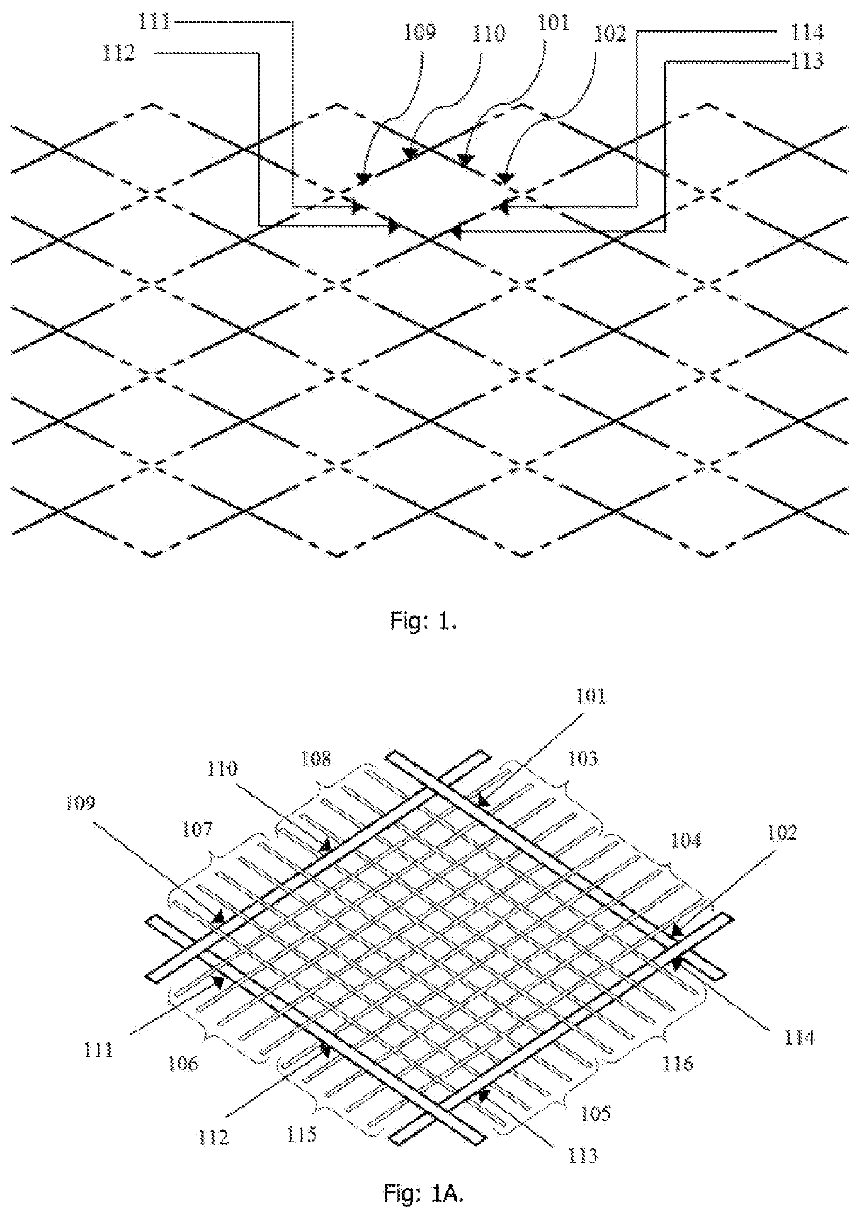
[0018]The present invention of the flow diverter device has a novel braiding pattern using two sets of wires in which the second set has thicker wire with higher stiffness. The wires used for braiding could be of Nitinol, which is superelastic and can recover its shape from large strains. The invention could be manufactured by conventional braiding process using a mandrel of suitable diameter and geometry. By changing the number of wires, braid angle and thickness of the wires (stiffer wire with flexural rigidity; here after mentioned as thicker wire), the porosity can be varied as per the requirement for flow diversion. The thicker wires are braided together with the finer wires in an interleaved fashion, wherein the thicker wires passes over a multiplicity of finer wires which are braided continuously, on one side before crossing over to the other side of the finer wires.

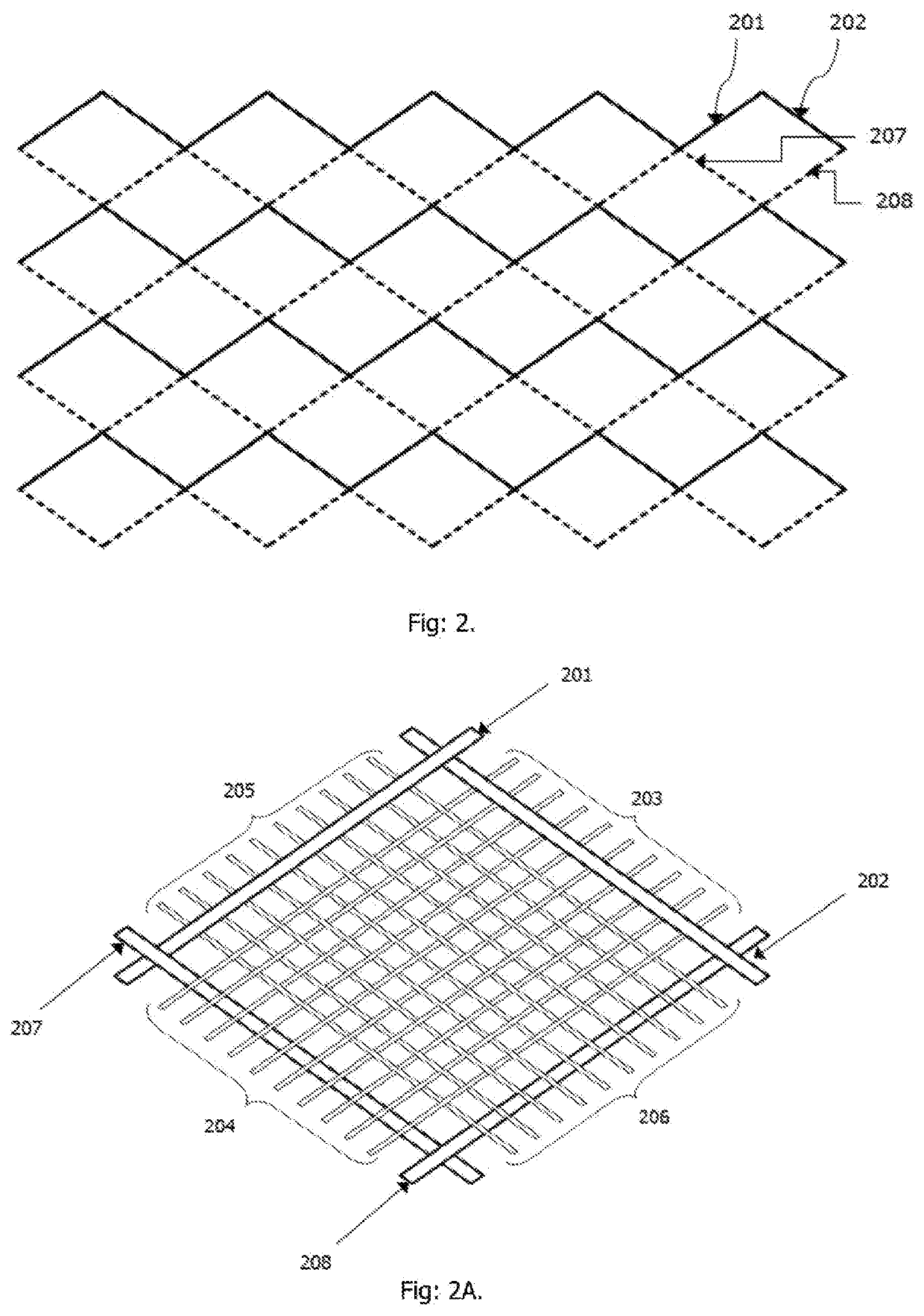
[0019]The present invention with the checker-board pattern when unfolded and laid flat horizontally:

[0020]has b...


PUM


Abstract

A flow diverter device is used to redirect the blood flow inside the cerebral blood vessels and for the reduction of blood flow to the aneurysm, hence preventing the chance of aneurysm rupture as well as promoting the healing of the aneurysm. The novel design of the device, using a set of thicker wires, provides high kink resistance and radial strength. Two patterns of inter-braiding the thicker set of wires with the finer braid are disclosed, one having a checker-board and the other a ring structure. Both patterns are highly kink resistant with the checker-board design providing minimal loss in flexibility, whereas the ring design provides greater radial strength. The device could be made of super elastic materials like Nitinol wires with the thicker set being radio opaque. The device is highly kink resistant and sufficiently flexible for use in vasculature with complex bends.

Description

FIELD OF INVENTION[0001]The present invention relates to a self expanding flow diversion device with enhanced kink resistance and radial strength. More particularly the present invention relates to a intravascular medical device called as a self expanding flow diverter employed for diverting the flow within the parent vessel itself.BACKGROUND OF THE INVENTION[0002]The term intracranial aneurysm refers to any localized ballooning or dilation of an artery in the brain. Since the wall of the dilated portion in the vessel experiences continuous blood flow, the inner muscles of the vessel (intima) can weaken progressively increasing the probability of aneurysm rupture resulting in a hemorrhagic stroke, which could be severely debilitating and fatal. So flow diversion is essential for rectifying such issues.[0003]The patent document US0021816A1 (2007) describes that intracranial aneurysm is initiated and developed by hemodynamic interactions between blood flow and vessel wall. An abnormal...

Claims


Application Information

Patent Timeline
IPC IPC(8): A61F2/90A61F2/06
CPCA61F2/90A61F2002/823A61F2002/068A61F2/06A61F2250/0039A61F2250/0098A61F2250/0017A61F2250/0036
Inventor SREEDHARAN, SUJESHSREEKUMAR, ANKUNAIR, SREEHARI UNNIKRISHNAN
Owner SREE CHITRA TIRUNAL INST FOR MEDICAL SCI & TECH
Why Eureka
Try Eureka