Heater protective tube for molten metal holding furnace

Active Publication Date: 2018-03-08
TOUNETSU CO LTD
View PDF5 Cites 0 Cited by
  • Summary
  • Abstract
  • Description
  • Claims
  • Application Information

AI Technical Summary

Benefits of technology

The heater protection tube described in this patent helps to keep molten metal at a low temperature as it moves from the inside of a furnace to the outside of the furnace. This is achieved by reducing the cross-sectional area at a boundary between two parts of the tube, which limits the heat transfer. This results in a more efficient heat dissipation and retention within the furnace, improving the overall process.

Problems solved by technology

If the temperature of the proximal end portion of the heating tube were lowered to a temperature far less than 550 degrees Celsius, an amount of heat released from the proximal end portion of the heating tube increases, which is disadvantageous in terms of thermal efficiency.
This arrangement is advantageous in terms of heat radiation, but it might be disadvantageous in terms of heat retention.

Method used


Image

  • Heater protective tube for molten metal holding furnace
  • Heater protective tube for molten metal holding furnace
  • Heater protective tube for molten metal holding furnace

Examples


Embodiment Construction

[0028]A molten metal holding furnace of one embodiment according to the present invention will now be described with reference to the accompanying drawings. In the description of the molten metal holding furnace, portions thereof located inside and outside the furnace are indicated by accompanying positional languages “inside” and “outside”, respectively. In the description of a heating tube inserted through a furnace wall of the molten metal holding furnace, portions of the heating tube located inside and outside the furnace are indicated by accompanying positional languages such as “distal” and “proximal,” respectively.

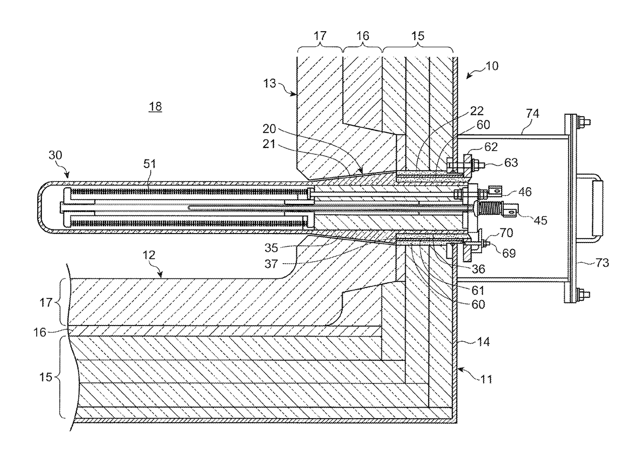
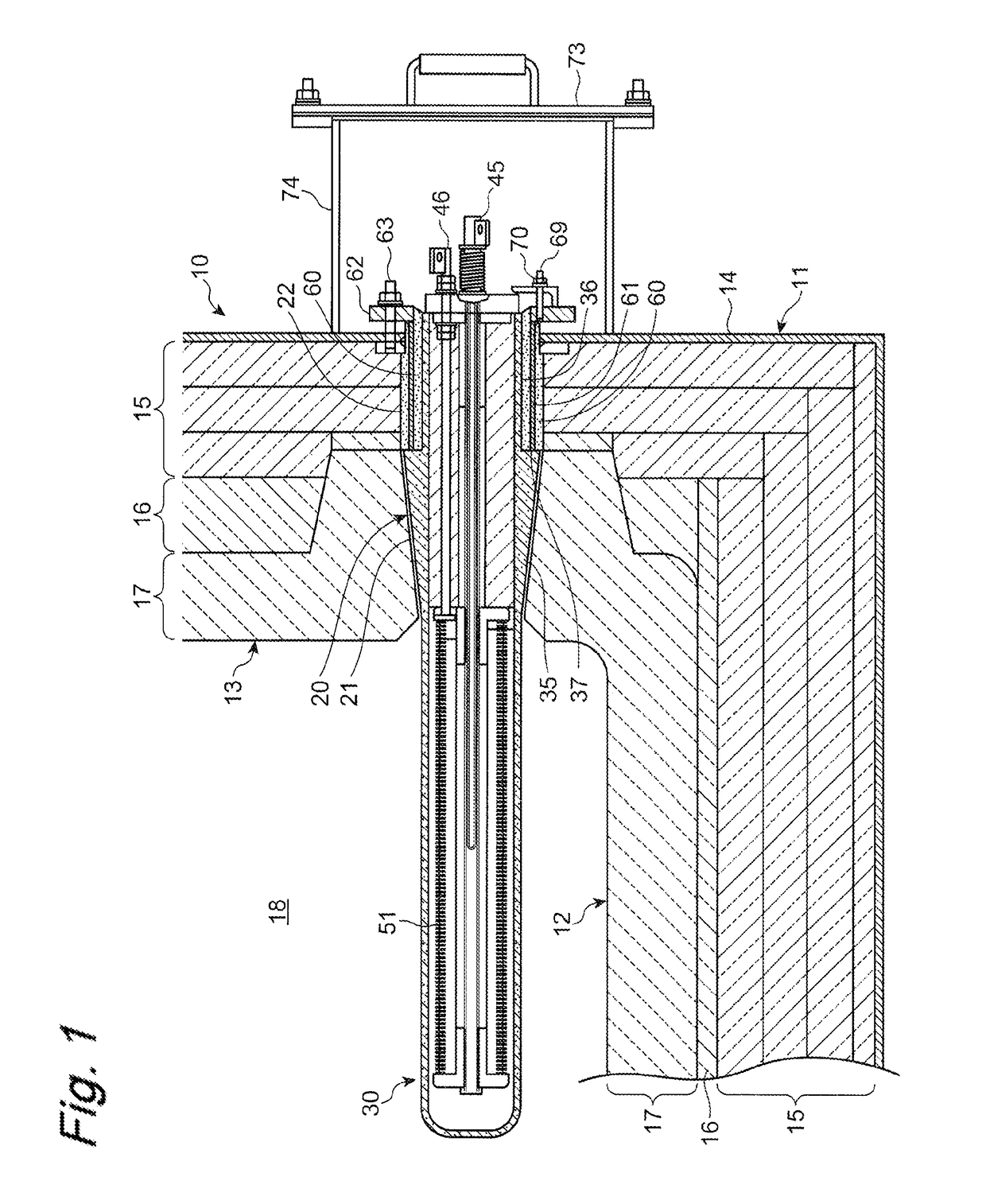
[0029]FIG. 1 is a cross-sectional view of a portion of a molten metal holding furnace 10 for holding a molten metal such as aluminum. The furnace 10 includes a furnace body 11. Similar to the conventional molten metal holding furnace, the furnace body 11 is made up of a bottom wall 12 and a peripheral or side wall 13 extending upwardly from the periphery of the bott...


PUM

PropertyMeasurementUnit
aaaaaaaaaa

Abstract

Provided is a heater protection tube for use with a molten metal holding furnace with heat dissipation and insulating properties. A heat protection tube 31 has a distal tapered cylindrical portion 35 corresponding to the inside tapered cylindrical portion 21 and a proximal non-tapered cylindrical portion 36 corresponding to the outside non-tapered cylindrical portion 22. The heater protection tube (31) is configured so that it can be mounted in the side wall (13) with the distal tapered cylindrical portion (35) located at the inside tapered cylindrical portion (21) and with the proximal non-tapered cylindrical portion (36) located at the outside non-tapered cylindrical portion (22).

Description

TECHNICAL FIELD[0001]The present invention relates to a heater protection tube for use with a molten metal holding furnace for holding a molten metal.BACKGROUND ART[0002]Conventionally, there has been disclosed a molten metal holding furnace for holding a molten metal of aluminum in patent document 1. The molten metal holding furnace disclosed in Patent Document 1 has a furnace body for holding a molten metal. The furnace body has a side wall formed with a hole through which a heating tube is inserted into the molten metal.[0003]Another heating tube which is available for the molten metal holding furnace is disclosed in patent document 2.PRIOR ART DOCUMENTSPatent Documents[0004]Patent Document 1: JP 2013-170801 A[0005]Patent Document 2: JP 5371784 B[0006]Each of the molten metal holding furnaces disclosed in patent documents 1 and 2 uses the transversely immersed heating tube to heat the molten metal through natural convection, which is advantageous in that the molten metal is not e...

Claims


Application Information

Patent Timeline
IPC IPC(8): H05B3/44F27B3/20F27D99/00H05B3/66F22B3/08F27D11/02H05B3/82
CPCH05B3/44F27B3/20F27D99/0006H05B3/66F22B3/08F27D11/02H05B3/82B22D45/00B22D41/01F27D2099/0013
Inventor MOCHIZUKI, KIYATA
Owner TOUNETSU CO LTD
Why Eureka
Try Eureka