Filter device

Inactive Publication Date: 2008-09-25
FRESENIUS MEDICAL CARE DEUTSCHLAND GMBH
View PDF5 Cites 0 Cited by
  • Summary
  • Abstract
  • Description
  • Claims
  • Application Information

AI Technical Summary

Benefits of technology

[0008]This object is achieved according to the present invention by a filter device whose membrane is designed in the form of a hollow fiber bundle, its fiber cavities forming a first flow space, with at least one inflow or outflow chamber which communicates with the first flow space being provided for supplying a medium to the hollow fiber bundle or removing a medium from it, said chamber being adjacent to an essentially circular or semicircular channel which communicates with an inlet or outlet of the filter device and is designed to be open in the direction of the ends of the hollow fibers, said channel being arranged approximately centrally with the hollow fiber bundle, having a cross-sectional area that decreases in the direction of flow and having an outside diameter smaller than the diameter of the hollow fiber bundle. This yields, first, the advantage that the blood flow undergoes only relatively gentle and low-stress changes in direction and velocity of flow. With the device according to the present invention, the flow velocity in the path through the essentially circular or semicircular channel gradually approaches the value of the velocity inside the fibers with the device according to the present invention.
[0012]According to a preferred embodiment of the present invention, the height and / or width of the channel decreases in the direction of flow. It is especially advantageous if the cross-sectional area of the channel decreases linearly with the flow path. Such a design yields the result that identical quantities of liquid or blood are discharged from the channel per angle area, thus resulting in a distribution that has approximate radial symmetry.
[0018]The guide elements may be designed as curved ribs. This makes it possible to distribute the fluid, in particular the blood, uniformly and in a defined manner. This may lead to the development of a small central vortex, but it always has radial symmetry.
[0025]The mouths of the connections may lie in one plane or in parallel planes. The corresponding design depends essentially on the mount holding the filter device, which should permit rapid and reliable replacement of the filter devices. In another embodiment of the present invention, the connections point in opposite directions.

Problems solved by technology

One problem with the design of the inflow and / or outflow chambers connected to the first flow space, i.e., to the hollow fiber bundle, is how to distribute the liquid so that it is apportioned evenly to the individual fibers of the hollow fiber bundle, and so that dead zones in the distribution of liquid are avoided.
This generally yields the disadvantage that use of the fibers varies greatly, and at the same time there are areas where the flow velocity is approximately zero (dead zones).
In addition, there is a great difference between the flow velocity in the inlet and that in the fibers.
This achieves uniform loading of the fibers but also results in a relatively low capacity or suboptimal utilization of the filter device on the whole due to the lack of hollow fibers at the center of the casing.
Due to the small amount of available space and the manufacturing restrictions due to the injection molding process, only an abrupt change of directions is possible in general, but that would constitute a considerable burden on the blood.

Method used


Image

  • Filter device
  • Filter device
  • Filter device

Examples


Embodiment Construction

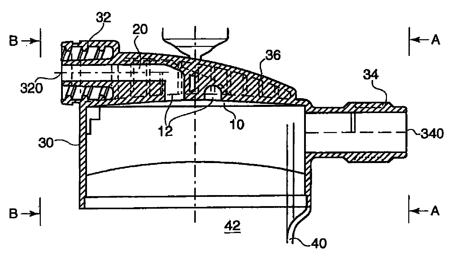
[0042]FIG. 1 shows a longitudinal sectional diagram of the end cap 30, which is in fluid-tight connection with the casing 40. End cap 30 has inflow or outflow chamber 10 adjacent to the semicircular channel 12. Liquid leaving semicircular channel 12 is carried into the inflow or outflow chamber 10 and is distributed in an essentially radially symmetrical pattern over the ends of the hollow fibers of a hollow fiber bundle.

[0043]Channel 12 is connected to the inlet or outlet 20 which in its end area forms the mouth 320 of connection 32 of the filter device according to the present invention.

[0044]End cap 30 is provided with bead 36 which extends radially, with connection 32 being formed in its end area.

[0045]In the area of end cap 30 shown at the right in FIG. 1, connection 34 is provided, having mouth 340 which is connected to the second flow space formed by the interior 42 of the casing surrounding the fibers.

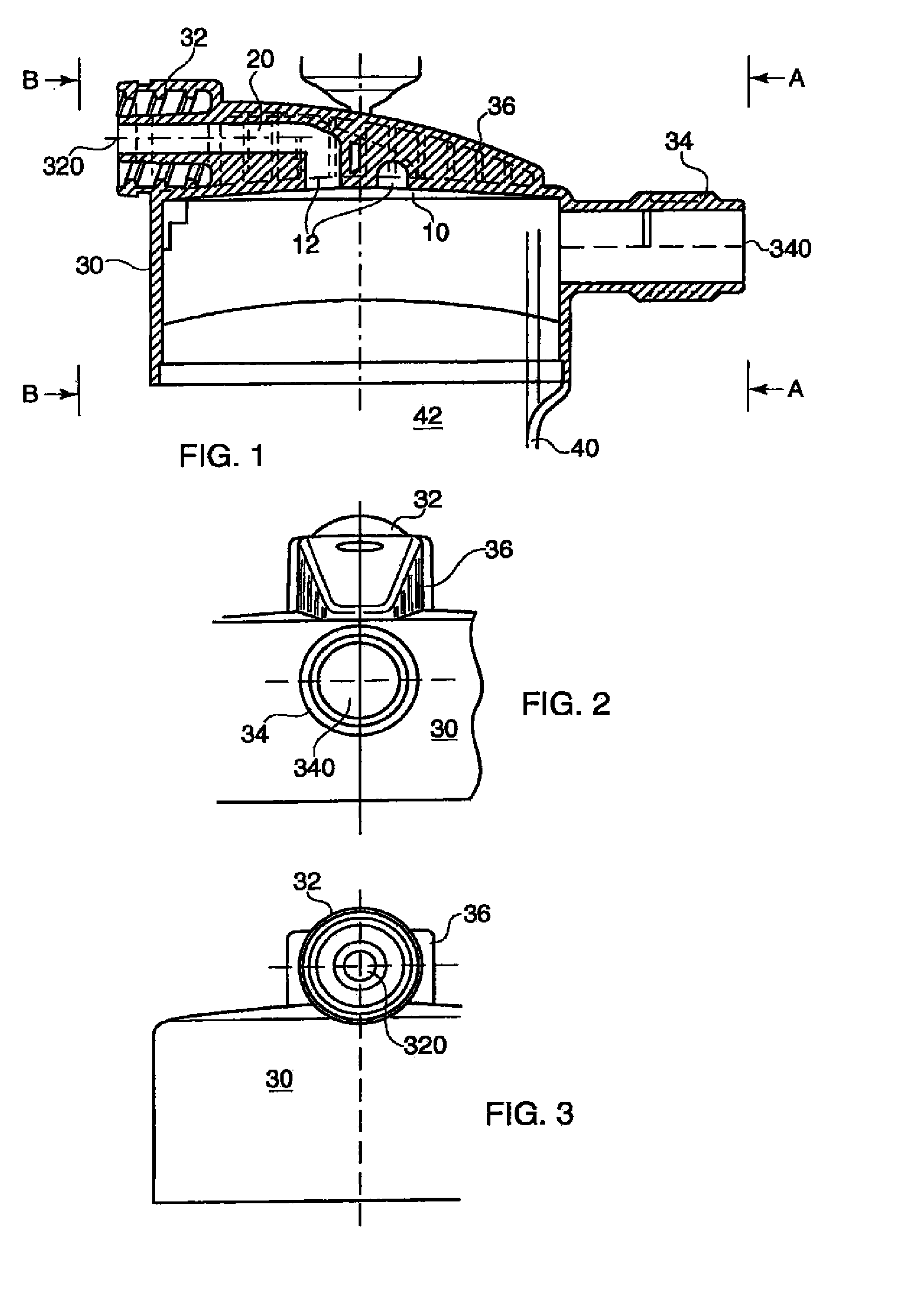
[0046]FIGS. 2 and 3 show the side views of the end cap 30 according to FIG...


PUM

PropertyMeasurementUnit
Flow rateaaaaaaaaaa
Diameteraaaaaaaaaa
Widthaaaaaaaaaa

Abstract

A filter device for mass exchange between two media separated by a membrane providing a low-stress transfer of blood flow from the connection area of the filter device to the fibers of a hollow fiber bundle is disclosed. Relatively uniform utilization of the fibers is provided by a membrane in the form of a hollow fiber bundle whose fiber cavities form a first flow space, with at least one inflow or outflow chamber connected to the first flow space being provided for supplying a medium to the hollow fiber bundle or removing a medium from the hollow fiber bundle. The inflow or outflow chamber is adjacent to an essentially circular or semicircular channel which is designed to be open in the direction of the ends of the hollow fibers and is connected to an inlet or outlet of the filter device. The channel is arranged approximately centrally with the hollow fiber bundle and preferably has a cross-sectional area that decreases in the direction of flow, and also preferably has an outside diameter that is less than the diameter of the hollow fiber bundle.An end cap for a filter device is also provided which as an inflow or outflow chamber adjacent to an essentially circular or semicircular channel designed to be open in the direction of the ends of the hollow fibers of a hollow fiber bundle arranged in a filter device casing connectable to the end cap. The essentially circular or semicircular canal is connected to an inlet or outlet of the end cap, arranged approximately centrally with the hollow fiber bundle, has a cross-sectional area that decreases in the direction of flow, and has an outside diameter that is smaller than the inside diameter of the area of the end cap which holds the hollow fiber bundle.

Description

FIELD OF THE INVENTION[0001]The present invention concerns a filter device for mass exchange between two media separated by a membrane and an end cap for such a filter device.BACKGROUND OF THE INVENTION[0002]such filter devices are generally used as dialyzers, hemofilters or ultrafilters. The filter devices generally consist of a casing in the form of a tubular section with end caps in its end areas. A tubular fiber bundle which functions as a membrane is usually arranged in the casing so that a reliable seal is provided between the first flow space formed by the fiber cavities and a second flow space surrounding the membrane on the outside.[0003]One problem with the design of the inflow and / or outflow chambers connected to the first flow space, i.e., to the hollow fiber bundle, is how to distribute the liquid so that it is apportioned evenly to the individual fibers of the hollow fiber bundle, and so that dead zones in the distribution of liquid are avoided.[0004]There are known di...

Claims


Application Information

Patent Timeline
IPC IPC(8): B01D61/14B01D63/02B01D69/08A61M1/18A61M1/16B01D46/24B01D61/30B01D65/00
CPCA61M1/16B01D46/0004B01D61/30B01D2313/21B01D65/00B01D2265/05B01D2313/06B01D63/02
Inventor HEILMANN, KLAUSBREITH, GERHARDRAIKO, IGORSANDER, ROLANDFRITZSCHE, STEFFEN
Owner FRESENIUS MEDICAL CARE DEUTSCHLAND GMBH
Why Eureka
Try Eureka