Heat-reactive switch

Active Publication Date: 2017-04-13
UBUKATA IND CO LTD
View PDF7 Cites 0 Cited by
  • Summary
  • Abstract
  • Description
  • Claims
  • Application Information

AI Technical Summary

Benefits of technology

The heat-reactive switch described in this patent allows for a larger heating value by having a smaller cross-sectional area and longer overall length of the heater. This is achieved by optimizing the shape of the heater.

Problems solved by technology

However, since the kind of metals used as bimetal and tri-metal of the heat-reactive plate is limited, for example, there is a limit to increasing the heating value by improving materials of the heat-reactive plate.
However, since a drive power for opening and closing a movable contact needs to be secured for the heat-reactive plate, there is also a limit to forming the heat-reactive plate thin.
Additionally, the kind of metal used as the material of the heater is also limited due to the required physical characteristics such as weldability and cost requirements.
Hence, there is substantially a limit to replacing the material of the heater with a material having high resistivity.

Method used


Image

  • Heat-reactive switch
  • Heat-reactive switch
  • Heat-reactive switch

Examples


Embodiment Construction

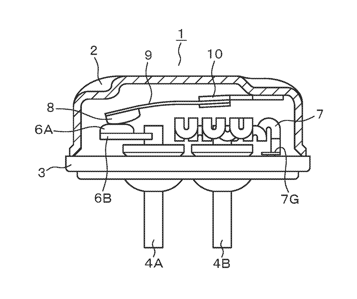
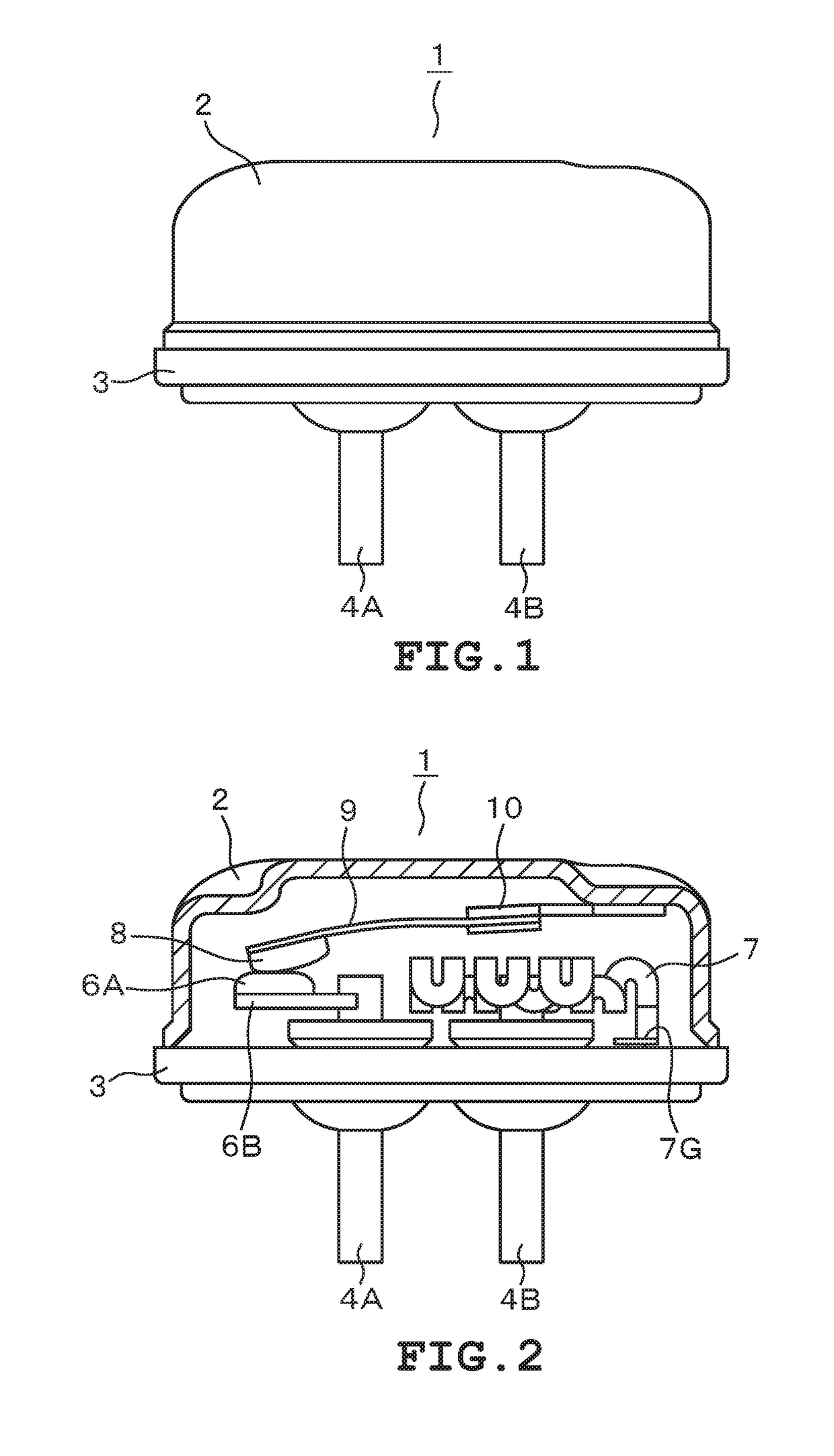
[0018]Hereinbelow, a description will be given of an embodiment of a heat-reactive switch to which the present invention is applied, with reference to the drawings. As shown in FIGS. 1 and 2, a heat-reactive switch 1 is an airtight container configured of a metallic housing 2 and a lid plate 3. The housing 2 is formed into a long dome shape having an open end. The lid plate 3 is adhered in an airtight manner to the open end of the housing 2 by welding, for example. Metallic conductive terminal pins 4A, 4B are inserted into two through holes provided in the lid plate 3. These conductive terminal pins 4A, 4B are fixed by an electrical insulating filler such as glass. Thus, the conductive terminal pins 4A, 4B are adhered in an airtight manner, in an electrically insulated state.

[0019]A fixed contact 6A is fixed, through a conductive fixed contact support 6B, to a part of one conductive terminal pin 4A on the inner side of the airtight container. Also, a heat-reactive plate 9 configured...


PUM


Abstract

A heat-reactive switch includes an airtight container with a housing and a lid plate, two conductive terminal pins fixed in through-holes in the lid plate, a fixed contact point fixed on one of the conductive terminal pins, a heater connected to the other conductive terminal pin and to the lid plate, a heat-reactive plate connected to the housing internal surface, the bending direction becoming inverted at a predetermined temperature, and a mobile contact point provided at the end of the heat-reactive plate. A heating element has a plurality of serpentine portions made from a metal plate in ribbon form, disposed between the lid plate and the heat-reactive plate so as to be parallel thereto. At least two of the serpentine portions are disposed to face each other while sandwiching the conductive terminal pin. Each portion follows the inner peripheral surface of the housing and have planar portions facing each other.

Description

CROSS-REFERENCE TO RELATED APPLICATIONS[0001]This is a National Stage Entry into the United States Patent and Trademark Office from International PCT Patent Application No. PCT / JP2014 / 063705, having an international filing date of May 23, 2014, the entire contents of which are incorporated herein by reference.FIELD OF THE INVENTION[0002]The present invention relates to a heat-reactive switch used as a protective device of a motor or the like.DESCRIPTION OF RELATED ART[0003]Conventionally, many heat-reactive switches using a heat-reactive body such as bimetal have been proposed as the type of heat-reactive switch mentioned above. A configuration of such a heat-reactive switch as an example will be described with reference to FIGS. 6 and 7. A heat-reactive switch 101 has a metallic housing 102 and a lid plate 103. An airtight container is formed by welding and fixing the lid plate 103 to an opening part of the housing 102. Through holes are provided in the lid plate 103. Metallic cond...

Claims


Application Information

Patent Timeline
IPC IPC(8): H01H37/34H01H37/04
CPCH01H37/04H01H37/34H01H37/14H01H37/5418H01H37/5427H01H61/00H01H85/165H01H2223/002
Inventor HORI, TOMOHIROYAMAGUCHI, YOSHIO
Owner UBUKATA IND CO LTD
Why Eureka
Try Eureka