Portable uv-c pathogen inactivation apparatus for human breathing air

a technology of inactivation apparatus and uvc, which is applied in the field of personal protective equipment, can solve the problems of airborne viruses or bacteria that are not completely stopped by particulate filters, the effect of reducing moisture content, high reflectivity, and reducing the size of most viruses

Inactive Publication Date: 2021-12-02
MEADOWSTAR ENTERPRISES
View PDF0 Cites 0 Cited by
  • Summary
  • Abstract
  • Description
  • Claims
  • Application Information

AI Technical Summary

Benefits of technology

[0008]An embodiment of the present invention provides a pathogen inactivation apparatus that includes a closed hollow shell surrounding an inner volume inside the shell (here, a wall of the shell is fluidly impermeable). The embodiment also includes first and second fluid ports, at the shell, that have corresponding first and second axes. The fluid ports provide fluid connections between the inner volume and an outside of the shell. The embodiment additionally includes an optical port that is fluidly sealed at the shell and has a third axis and being configured to deliver target light in the UV-C spectral band from the outside of the shell towards the inner volume. The inner volume contains an optical element configured to recirculate the target light within the inner volume by redirecting a flux of the target light, received in the inner volume through the optical port, across the inner volume multiple times. In a specific case, such optical element may include an optical thin-film coating characterized by high reflectivity at a wavelength of the target light. (Such coating is present at least on portions of an inner surface of the wall that are transverse to the third axis). Additionally or in the alternative, the first and third axes may be substantially transverse to one another, while the embodiment includes comprising first and second baffles affixed to an inner surface of the wall to extend along the second axis such as to block a direct flow of fluid, received in the inner volume from the at least on fluid port, along the first axis and to redirect this flow into a channel formed between the first and second baffles and extending along the third axis. (in the specific implementation of the latter case, at least one of the following conditions may be satisfied:—the third axis may be defined to traverse the channel without crossing either of the first and second baffles; and—the second and third axes may be substantially transverse to one another. (If an when the inner surface of the wall is defined by a substantially cylindrical surface coated with a thin-film coating with high reflectivity at a wavelength of the target light, the inner surface with the coating is structured to reflect the target light along the channel between the first and second baffles.) In at least one implementation, the apparatus may be configured such as to satisfy at least one of the following conditions: i) at least one of the first and second baffles is substantially opaque at an operational wavelength of the target light, ii) at least one of the first and second baffles is highly-reflective at the operational wavelength; iii) the apparatus includes a beam-shaping optics affixed to the wall inside the inner volume an juxtaposed against the optical port; and / or to further comprise a facemask having a mask input port either directly or through a tubular member physically and fluidly connected with the second fluid port of the shell. Alternatively or in addition, the inner volume may be sub-divided to define a first sub-volume, a second sub-volume, and a third sub-volume (where the first and second sub-volumes are fluidly connected with one another only through a first gap formed in a first fluidly-impermeable partition extended across the inner volume along the third axis or between the first partition and the wall, and where the second and third sub-volumes are fluidly connected with one another only through a second gap formed in a second fluidly-impermeable partition extended across the inner volume along the third axis or between the second partition and the wall.) In such latter case, the first gap may be formed in a first portion of the inner volume that adjoins the optical port and the second gap is located in a second portion of the inner volume that is opposite to the optical port to define a path of fluid, received by the inner volume from the first fluid port and propagating towards the second fluid port, to extend along the third axis in the second sub-volume to maximize an overlap with a flux of target light received by the inner volume through the optical port. Alternatively or in addition, the apparatus may be configured to deliver an infrared (IR) irradiation into the inner volume to reduce moisture content from fluid entering the inner volume through one of the first and second fluid ports.
[0009]Embodiments of the invention additionally provide a method for operating a pathogen deactivation apparatus. The method includes the step of: transmitting air from the outside of the shell through the first fluid port into a first sub-volume of the inner volume, the first sub-volume being separated from a second sub-volume of the inner volume with a first substantially fluidly-impermeable screen that is configured to extend along the third axis and to define a first gap either in the first screen or between said first screen and the wall. The method additionally includes the step of passing the air along the third axis between said first screen and a second substantially fluidly-impenetrable screen that separates the second sub-volume of the inner volume from a third sub-volume of the inner volume, where the second screed is configured to extend along the third axis and to define a second gap either in the second screen or between said second screen and the wall. The method further includes the step of irradiating the air during the process of passing of the air through the second sub-volume with the target light (that has been delivered through the optical port into the second sub-volume) while recirculating said target light inside the second sub-volume by multiply reflecting such delivered target light at an optical member disposed in the inner volume to form inactivated air. In at least one case, the method also includes moving the air, that has passed through the second gap, through the second fluid port and through a facemask fluidly cooperated with the second fluid port, and / or (upon utilizing the air by a user wearing the facemask) expelling used air through the second fluid port to transmit said used air through the second gap while irradiating such used air with the target light being multiply reflected within the second sub-volume to form inactivated used air. The method may further include a step of irradiating the air during passing of said air through the inner volume to reduce a level of moisture in said air.

Problems solved by technology

However, most viruses are smaller in dimension than the mesh size of these particulate filters.
A logical conclusion is that as the droplets decrease in size due to the water in the mucus evaporating, and the droplet size continues to decrease rendering the particulate filter at least less effective (and probably substantially ineffective.
Particulate filters in common use alone cannot completely stop viruses or bacteria which are airborne, especially as the carrier droplets decrease in size due to dehydration when expelled into the air.

Method used


Image

  • Portable uv-c pathogen inactivation apparatus for human breathing air
  • Portable uv-c pathogen inactivation apparatus for human breathing air
  • Portable uv-c pathogen inactivation apparatus for human breathing air

Examples


embodiment 100

[0020]FIG. 1A provides a schematic of an embodiment 100 of the air-sterilization apparatus, showing, in general, a sterilization unit 110, defining a fluidly sealed inner chamber or cavity (which may contain air baffles extending between the opposite sides of the chamber, as discussed below) and having an inlet port 112 through which an intake air flow (shown as IAF) can be received by the unit 110. The source 120 of UV-light (preferably juxtaposed with the heatsink 124 for removal of waste heat from the UV emitter of the source 12) is appended to a side of the sterilization unit 110 and radiatively connected with the inner volume (chamber) of the unit 110 via an appropriate optical port (not shown) to irradiate (130) the inside of the inner chamber with a virus-inactivating radiation and with it—the flow of air A passing through the unit 110. The axes of the inlet port 112 and of the optical port are substantially transverse to one another. The sterilized air SAF is fluidly passed ...
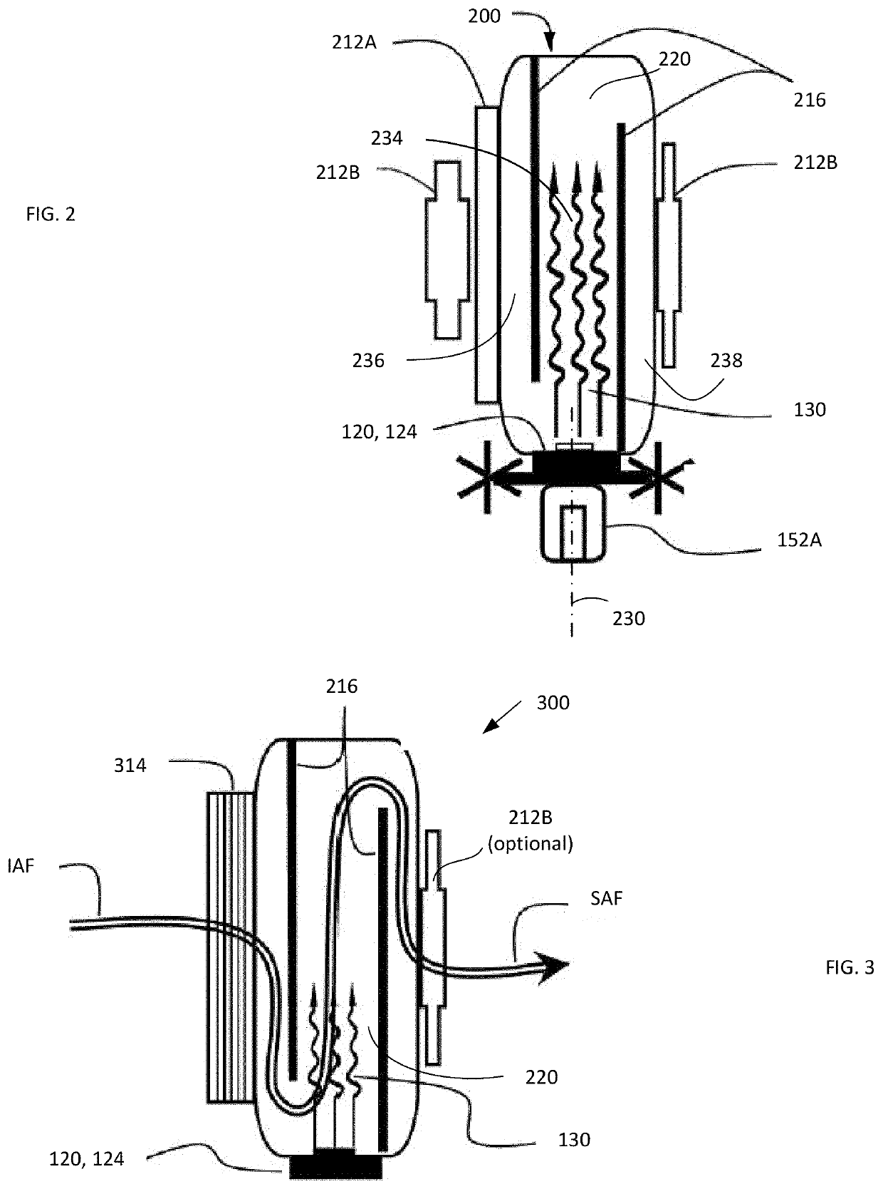
embodiment 200

[0025]FIG. 2 depicts an embodiment 200 of the air sterilization unit 110 of FIG. 1, showing the inlet port 112 with an air intake grill 212A and / or air intake hose connection 212B. The inner chamber 220 of the unit 200 is preferably equipped with contains one or more air flow baffles 216 that are positioned and dimensioned to direct (uniformly channel) the incoming air through the space of the chamber 220 irradiated (130) with UV-light from the source of UV radiation 120 and to minimize the shortcircuiting.

[0026]The source 120 preferably includes an UV-C light source such as, without limitation, one of those provided by Klaran Crystal IS Green Island N.Y. USA, Bolb, Inc Livermore Calif. USA, Seoul Viosys, Gyeonggi-do Republic of Korea, Shenzhen Guangmai Electronics Co. Ltd. Shenzhen Guangdong China, as known in the art. In a preferred embodiment, the source 120 is configured to contain at least one UV-C LED emitting light at wavelength(s) within the range of 250 nm . . . 290 nm with...

embodiment 300

[0037]The operational and dimensional characteristics of other constituent components and elements of the embodiment 300 may be chosen to be substantially the same as those discussed in reference to FIG. 2. The commercially available particulate filter 314 may be chosen to include N95 or P100, and HEPA filters for pathogen filtration. Such commercially available mask manufacturers selected from the group comprising 3M Company, St. Paul, Minn.; Mine Safety Appliances (MSA; Honeywell International Inc, Charlotte, N.C.; Jayco Safety Products Pvt. Ltd., Borivali, Mumnai, India; Draegerwerk AG & Co. KGaA, Lubeck, Germany; Gentex Corp, Zeeland, Mich., for example.

[0038]Depending on the specifics of design of filter 314, the air grill 212A may not be required, but the presence of the hose connector 212B may still be needed for ventilators, breathers, and CPAP machines. Information presented in FIGS. 11, 12 and Tables 2 and 3 is equally applicable to the operation of the embodiment 300.


PUM

PropertyMeasurementUnit
diameteraaaaaaaaaa
diameteraaaaaaaaaa
sizeaaaaaaaaaa

Abstract

System and method for pathogen inactivation with UV-C light (employed by itself or in addition to filtering out particulates rom the flow of air reaching the user) by delivering, into a lightguide portion of the air inactivation chamber of the system, a dose of ultraviolet radiation sufficient for at least one log reduction level of the pathogen while, at the same time, multiply reflecting the light inside the chamber to increase the irradiance of inactivating light several fold (up to 5×, or even up to 8.6×) as compared to that delivered to the chamber.

Description

CROSS REFERENCE TO RELATED APPLICATIONS[0001]This application claims priority from the U.S. Provisional Patent Applications Nos. 63 / 032,503 filed on May 29, 2020 and 63 / 039,778 filed on Jun. 16, 2020. The disclosure of each of the above-identified patent applications is incorporated herein by reference.TECHNICAL FIELD[0002]The present invention relates generally to personal protective equipment (PPE) and, more particularly, to an apparatus configured to inactivate pathogens present in breathing air instead of attempting to filter-out such pathogens.RELATED ART[0003]With the global pandemic of airborne pathogens such as COVID19, (SARS-CoV-2), and other calamities that will follow, there remains a persistent need in various PPE. Currently, filters devised to remove the particulate matter (interchangeably referred to herein as particulate filters) are being used to reduce risk of the spread of such diseases. These filters are rated pursuant to following Respirator Rating Number Class. ...

Claims


Application Information

Patent Timeline
Patent Type & Authority Applications(United States)
IPC IPC(8): A61L2/10A61L2/00A61M1/02A61M1/36
CPCA61L2/10A61L2/0011A61M2205/053A61M1/3681A61M2202/0415A61M1/0281A61L9/20A62B23/02A62B18/025
Inventor HOBOY, LOREN P.YARMIE, ALEXANDER J.DAVIS, RONALD T.
Owner MEADOWSTAR ENTERPRISES
Why Eureka
Try Eureka