
Computer-implemented method for testing a technical system

Pending Publication Date: 2021-11-25
ROBERT BOSCH GMBH
View PDF5 Cites 0 Cited by
  • Summary
  • Abstract
  • Description
  • Claims
  • Application Information

AI Technical Summary

Benefits of technology

The present invention provides a method for overcoming the limitations of conventional fault tree analysis by using embedded real-time determination and application of fuzzy logic. This method allows for a determination of the importance or criticality of each component in a technical system based on the priorities of base events. The technical system can then be adapted accordingly to reduce the likelihood of failure or increase product safety. The method requires relatively little computing time, making it feasible to use an embedded real-time microcontroller. Additionally, an abort criterion can be set based on the number of iterations.

Problems solved by technology

In this case, the failure even of one component results in a failure of the entire system.
However, it may sometimes be difficult to estimate an exact failure rate of the components when, for example, insufficient data, or indeterminate characteristics of the events, are present.
This plays a role due to the fact that insufficient data often make it difficult to objectively determine the likelihood.
However, indeterminate symptoms frequently occur which may usually be expressed only in the form of qualitative measures or linguistic variables such as “few,”“average,” or “many.” In fact, conventional mathematical methods, due to their indeterminate nature, cannot efficiently deal with natural linguistic expressions.
The conventional fault tree analysis is static, not real-time capable, not programmable, and the priorities of the base events are not unambiguous.

Method used


Image

  • Computer-implemented method for testing a technical system
  • Computer-implemented method for testing a technical system

Examples


Embodiment Construction

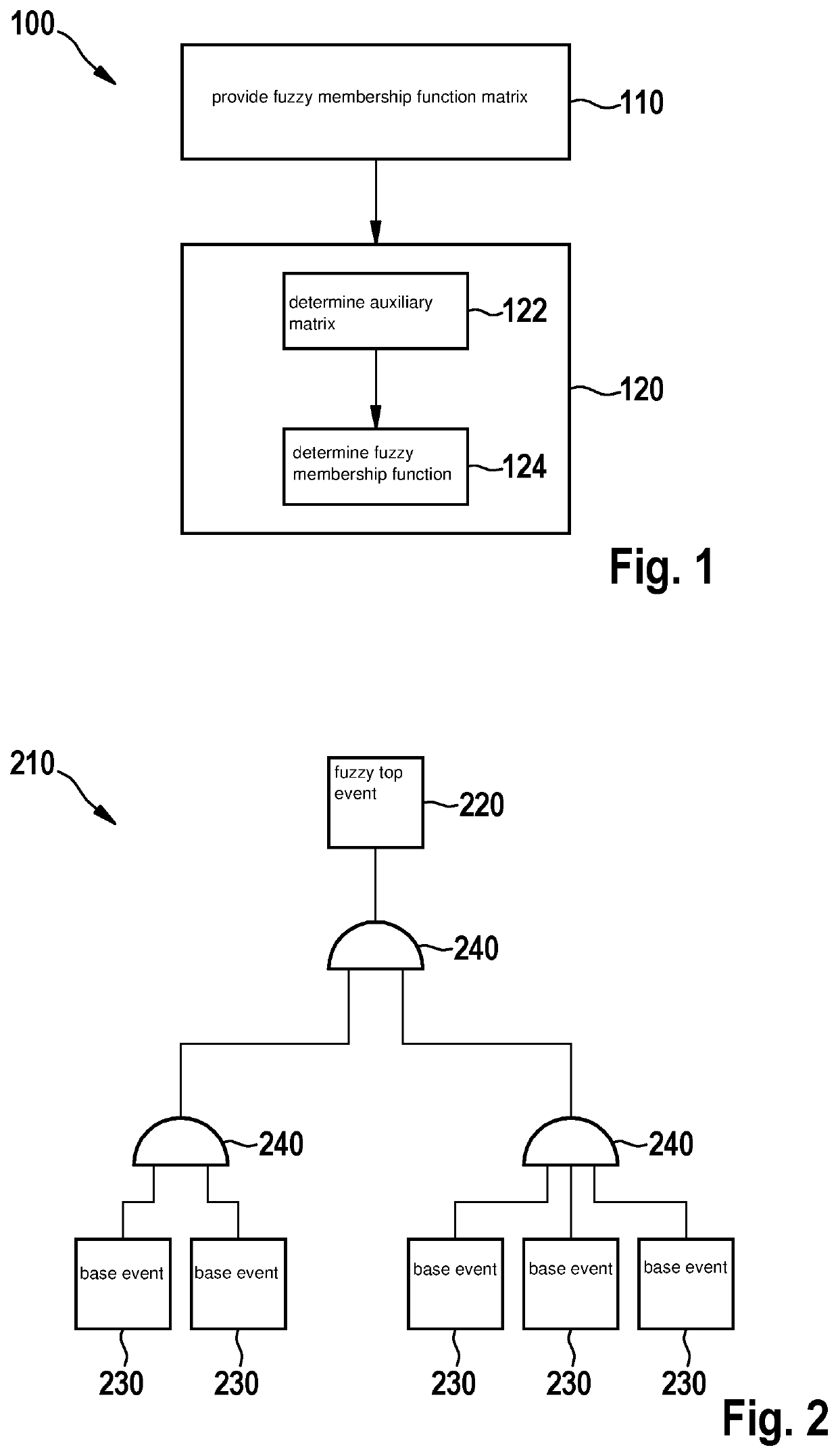
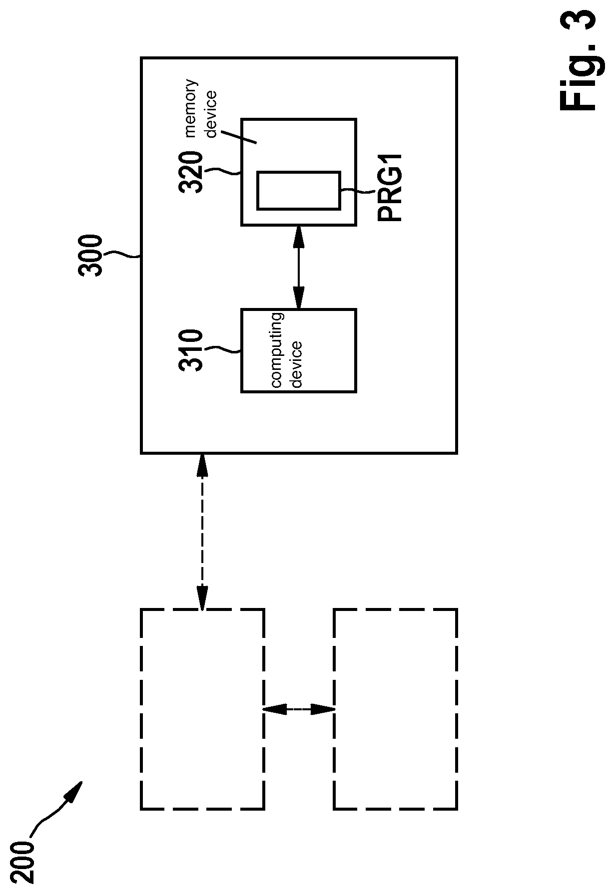
[0037]FIG. 1 shows a schematic illustration of steps of a method 100 in a flowchart. Method 100 is a method for testing a technical system 200 (cf. FIG. 3), in particular software, hardware, or an embedded system, in real time.

[0038]Technical system 200 includes a plurality of in particular technical components. A schematic illustration of a fuzzy fault tree topology 210 is shown in FIG. 2.

[0039]A fuzzy top event 220 is situated at the top of fuzzy fault tree topology 210. Fuzzy top event 220 represents an undesirable event, for example the total failure of the technical system.

[0040]Fuzzy top event 220 is ascertained within the scope of a hazard analysis, for example, and predefined by so-called requirements which describe the requirements for the reliability of technical system 200.

[0041]According to FIG. 1, five base events 230 are illustrated by way of example. Linkages between base events 230 are represented by logical AND operators and / or OR operators 240.

[0042]In method 100, ...


PUM


Abstract

A computer-implemented method for testing a technical system, in particular software, hardware, or an embedded system, in real time. The technical system encompasses a plurality of in particular technical components. The technical system is represented by a fuzzy fault tree topology Aki. Starting from a fuzzy top event Xk for determining priorities of base events, the following steps are carried out: providing a fuzzy membership function matrix Wiλ of the base events, where λ=1, and carrying out an iterative process, each iteration λ, where λ=1, 2, 3, . . . , n, encompassing the following steps: determining an auxiliary matrix Cki, taking into account the fuzzy top event Xk, the fuzzy fault tree topology Aid, and the fuzzy membership function matrix Wiλ, using an iterative algorithm, and determining (the fuzzy membership function matrix Wiλ+1 based on the auxiliary matrix Cki, using a maximum likelihood method.

Description

CROSS REFERENCE[0001]The present application claims the benefit under 35 U.S.C. § 119 of German Patent Application No. DE 102020206325.7 filed on May 20, 2020, which is expressly incorporated herein by reference in its entirety.BACKGROUND INFORMATION[0002]Fault tree analysis (FTA) is a conventional method for analyzing the error logic of a system and for computing the overall reliability.[0003]Fault tree analysis is based on a single undesirable event situated at the top of the fault tree, the so-called top event, which for example describes the total failure of the system and which is ascertained within the scope of a hazard analysis.[0004]Starting from this top event, the fault tree is created in a top-down analysis, all the way down to the individual failure states of the components. For more complex systems, a subdivision takes place into subsystems, which are analogously further subdivided until the entire system is mapped in the form of minimum sections, in the form of base ev...

Claims


Application Information

Patent Timeline
IPC IPC(8): G06F11/26G06N7/02
CPCG06F11/26G06N7/02G06F11/079G06F17/16G06F17/15G06N5/048G06N20/00G06N7/023G06N5/01G06F11/2263
Inventor BAKUCZ, PETERBORES, JAVIER
Owner ROBERT BOSCH GMBH
Learn More