Wavelength dispersion amount estimation apparatus
a technology of amount estimation and wavelength dispersion, which is applied in the direction of electrical equipment, fibre transmission, dispersion/dispersion elimination, etc., can solve the problems of tens of operation cost increase and wavelength dispersion, and achieve the effect of little computation tim
- Summary
- Abstract
- Description
- Claims
- Application Information
AI Technical Summary
Benefits of technology
Problems solved by technology
Method used
Image

Examples
first embodiment
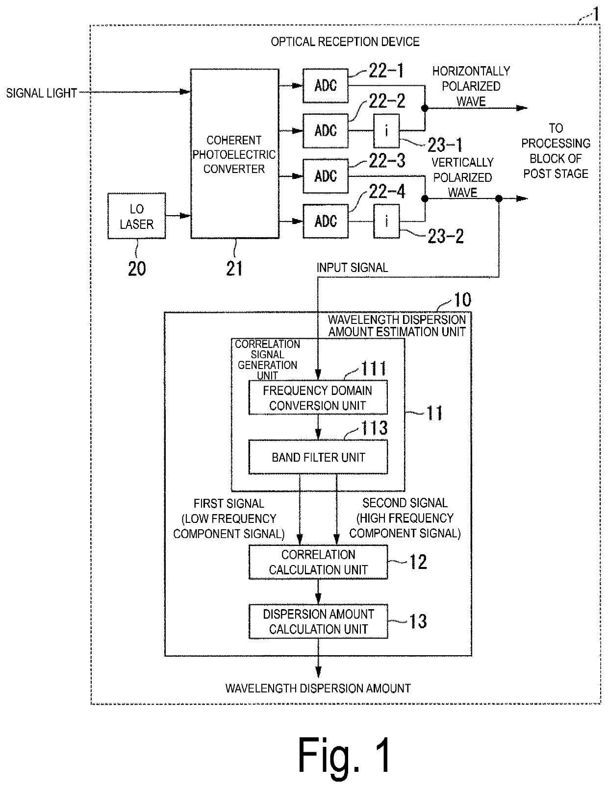
[0045]Embodiments of the present invention will be described below with reference to the drawings. FIG. 1 is a block diagram illustrating a configuration of an optical reception device 1 included in a wavelength dispersion amount estimation unit 10 (a wavelength dispersion amount estimation apparatus) according to a first embodiment. The optical reception device 1 is an optical reception device that receives signal light in a so-called digital coherent scheme and includes a local oscillator (LO) laser 20, a coherent photoelectric converter 21, analog-to-digital converters (ADCs) 22-1 to 22-4, imaginary unit multiplication units 23-1 and 23-2, and the wavelength dispersion amount estimation unit 10.
[0046]The LO laser 20 is a local oscillation laser, and outputs localized oscillating light having a phase matching the frequency of the signal light. The coherent photoelectric converter 21 uses the local oscillating light output by the LO laser 20 to perform optical homodyne coherent det...
second embodiment
[0108]FIG. 14 is a block diagram illustrating a configuration of a wavelength dispersion amount estimation unit 10b according to a second embodiment.
[0109]The same components as those according to the first embodiment are denoted by the same reference signs, and different components will be described below.
[0110]In the wavelength dispersion amount estimation unit 10 or 10a according to the first embodiment, the band filter unit 113 selects the high frequency band section 130 and the low frequency band section 131 for a single FFT frame, and generates a high frequency component signal and a low frequency component signal. Then, the correlation calculation unit 12 multiplies, for each element, a complex conjugate of either the high frequency component signal or the low frequency component signal with the other signal, and converts the result into the time domain by the IFFT to calculate the cross correlation. In this way, in the calculated cross correlation, a peak appears at a single...
third embodiment
[0134]FIG. 17 is a block diagram illustrating a configuration of a wavelength dispersion amount estimation unit 10c according to a third embodiment.
[0135]The same components as those according to the first embodiment are denoted by the same reference signs, and different components will be described below. The wavelength dispersion amount estimation unit 10c includes a correlation signal generation unit 11c, a correlation calculation unit 12c, and a dispersion amount calculation unit 13c. The wavelength dispersion amount estimation unit 10, 10a or 10b according to the first and second embodiments generates a signal for cross correlation in the frequency domain. In contrast, the wavelength dispersion amount estimation unit 10c according to the third embodiment generates a signal for cross correlation in the time domain.
[0136]The correlation signal generation unit 11c includes a branching device 115 (a splitter), an oscillator 116, a complex conjugate computation unit 117, multipliers...
PUM
 Abstract
Description
Claims
Application Information
 - R&D
- Intellectual Property
- Life Sciences
- Materials
- Tech Scout
- Unparalleled Data Quality
- Higher Quality Content
- 60% Fewer Hallucinations
Browse by: Latest US Patents, China's latest patents, Technical Efficacy Thesaurus, Application Domain, Technology Topic, Popular Technical Reports.
© 2025 PatSnap. All rights reserved.Legal|Privacy policy|Modern Slavery Act Transparency Statement|Sitemap|About US| Contact US: help@patsnap.com