
Friction transmission belt and production method therefor

a transmission belt and friction technology, applied in the direction of vegetal fibres, mechanical devices, other domestic objects, etc., can solve the problems deformation and tear of fibrous members, bending and breaking of pins of tenters, etc., to achieve excellent submerged performance, improve the releasability of the obtained precursor (composite fibrous layer sheet) from the pin, and reduce the effect of deterioration of transmission performan

Pending Publication Date: 2021-10-21
MITSUBOSHI BELTING LTD
View PDF35 Cites 0 Cited by
  • Summary
  • Abstract
  • Description
  • Claims
  • Application Information

AI Technical Summary

Benefits of technology

The present invention relates to a frictional power transmission belt which has excellent durability and low deterioration of transmission performance when submerged. The composite fibrous layer of the belt contains cellulose-based fiber, isocyanate compound, and resin component. The use of isocyanate compound and resin component in a specific ratio improves the noise suppression and wear resistance of the belt. The use of thermally reactive isocyanate compound improves the wear resistance of the belt without inhibiting the elongation of the knitted fabric. The immersion solution containing isocyanate compound and resin component is simple and environmentally friendly. The wear resistance of the belt can also be improved by adjusting the fibers constituting the fibrous member.

Problems solved by technology

However, in this V-ribbed belt, the cellulose-based natural spun yarns may fall off from the frictional power transmission surface as the belt is used and the abnormal noise may be likely to occur since the cellulose-based natural spun yarns having low wear resistance are essential, and therefore, this V-ribbed belt is required to be improved.
However, the fibrous member impregnated with the adhesive component is likely to have a decreased releasability from a pin of the pin tenter.
When the releasability from the pin is decreased, problems such as deformation and tearing of the fibrous member or bending and breaking of the pin of the tenter occur.
However, this method requires equipment changes and is not economical.

Method used

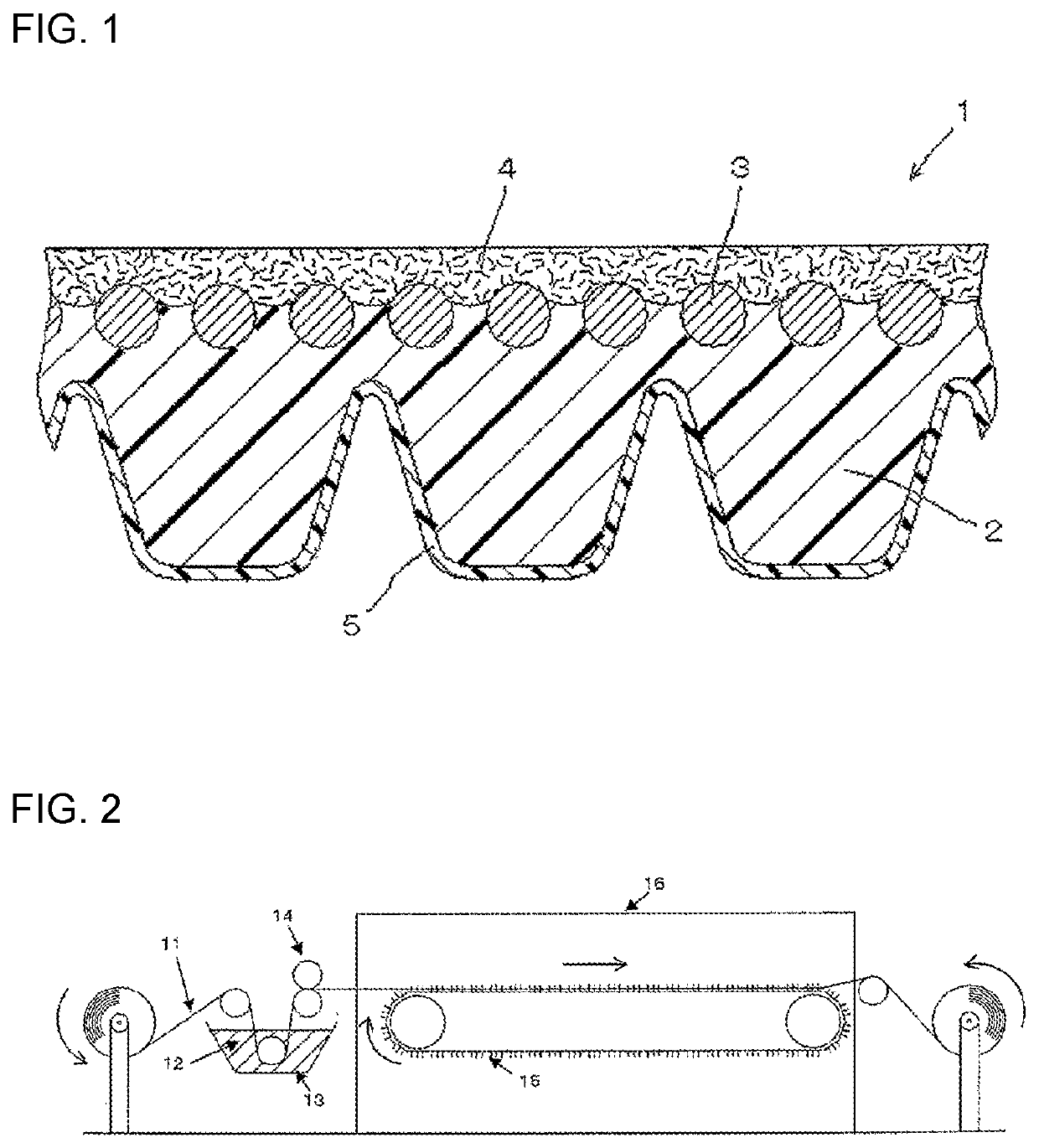
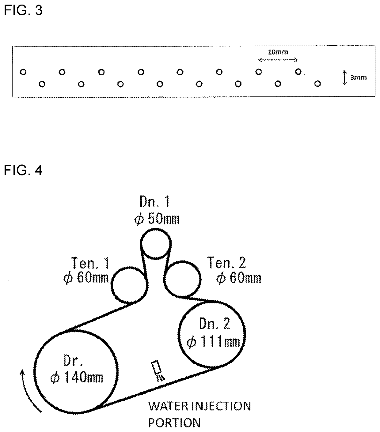

Image

  • Friction transmission belt and production method therefor
  • Friction transmission belt and production method therefor
  • Friction transmission belt and production method therefor

Examples


examples 1 to 7 and reference example 1

[Preparation of Thermally Reactive Isocyanate and Resin Component Impregnated Knitted Fabric]

[0154]In Examples 1 to 6 and Reference Example 1, a cotton spun yarn (yarn count: 40, one yarn) as a cellulose-based fiber and a PTT / PET conjugate composite yarn (fineness: 84 dtex) as a synthetic fiber were knitted at a mass ratio of cellulose-based fiber to synthetic fiber of 80 / 20 to produce a knitted fabric (fibrous member) whose knitted structure is weft knitting (moss stitch, two layers). The thickness of the obtained knitted fabric was 0.85 mm, and the density of the knitted fabric (wale+course) was 100 yarns / inch. A surface layer was formed of cellulose-based fibers, and an inner layer was formed of synthetic fibers.

[0155]In Example 7, a cotton spun yarn (yarn count: 40, one yarn) as a cellulose-based fiber and a PTT / PET conjugate composite yarn (fineness: 84 dtex) as a synthetic fiber were knitted at a mass ratio of cellulose-based fiber to synthetic fiber (cellulose-based fiber / syn...


PUM

PropertyMeasurementUnit
dissociation temperatureaaaaaaaaaa

Abstract

The frictional power transmission belt includes a frictional power transmission surface formed of a composite fibrous layer containing a fibrous member, an isocyanate compound, and a resin component, wherein the fibrous member contains a cellulose-based fiber. A proportion of each of the isocyanate compound and the resin component in the composite fibrous layer may be 2 to 15% by mass.

Description

TECHNICAL FIELD[0001]The present invention relates to a frictional power transmission belt (V-ribbed belt or the like) that has a frictional power transmission surface covered with fabric (knitted fabric or the like) and has high transmission efficiency and improved quietness (silence or noise suppression), and relates to a production method therefor.BACKGROUND ART[0002]Frictional power transmission belts are widely used for driving auxiliary equipment of automobiles and for driving agricultural machines. Examples of the frictional power transmission belts include a flat belt, a V-belt, and a V-ribbed belt, and the frictional power transmission belts are used separately from an engagement transmission belt represented by a toothed belt that transmits power through mechanical fitting between a pulley and a belt tooth portion. Some frictional power transmission belts have a frictional power transmission surface covered with a fibrous member in order to improve wear resistance or adjus...

Claims


Application Information

Patent Timeline
Patent Type & Authority Applications(United States)
IPC IPC(8): F16G5/06B29D29/10F16G5/20D06M15/564C08G18/54D01F8/02D01F8/04
CPCF16G5/06B29D29/10F16G5/20D06M2101/06C08G18/542D01F8/02D01F8/04D06M15/564C08G18/792C08G18/80C08G18/42F16G5/08D06M2101/16
Inventor HAMAMOTO, KOUHEITAKECHI, HIROKI
Owner MITSUBOSHI BELTING LTD
Learn More