
Methods and systems for evaporation of liquid from droplet confined on hollow pillar

a technology of droplet and liquid, which is applied in the field of liquid evaporation, can solve the problems of dielectric liquid, design aspects of electronic devices such as shape and size are limited, and current thermal management systems are not completely satisfactory in dissipating relatively high amounts of heat generated by electronic devices

Pending Publication Date: 2021-10-07
WASHINGTON UNIV IN SAINT LOUIS
View PDF0 Cites 1 Cited by
  • Summary
  • Abstract
  • Description
  • Claims
  • Application Information

AI Technical Summary

Benefits of technology

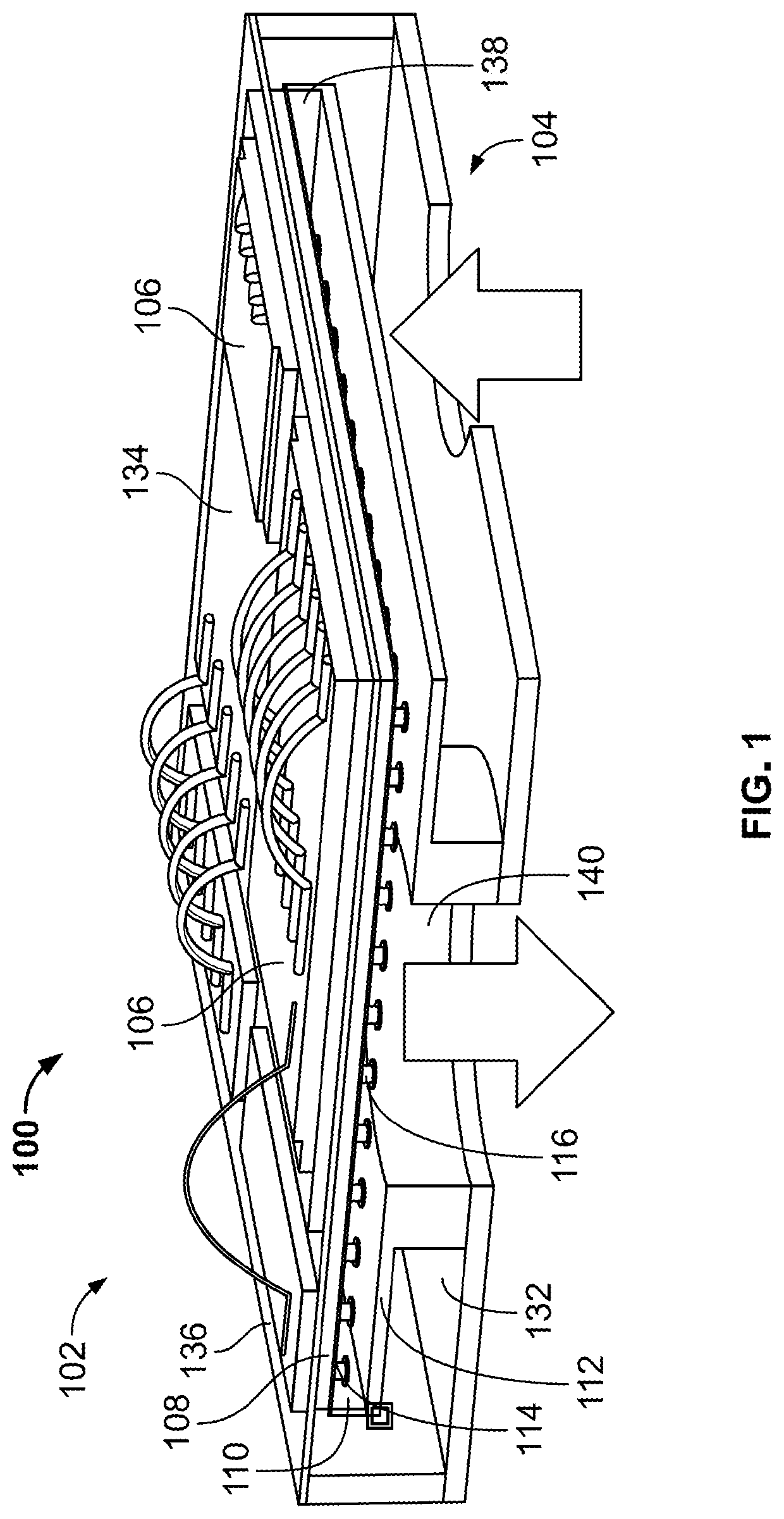
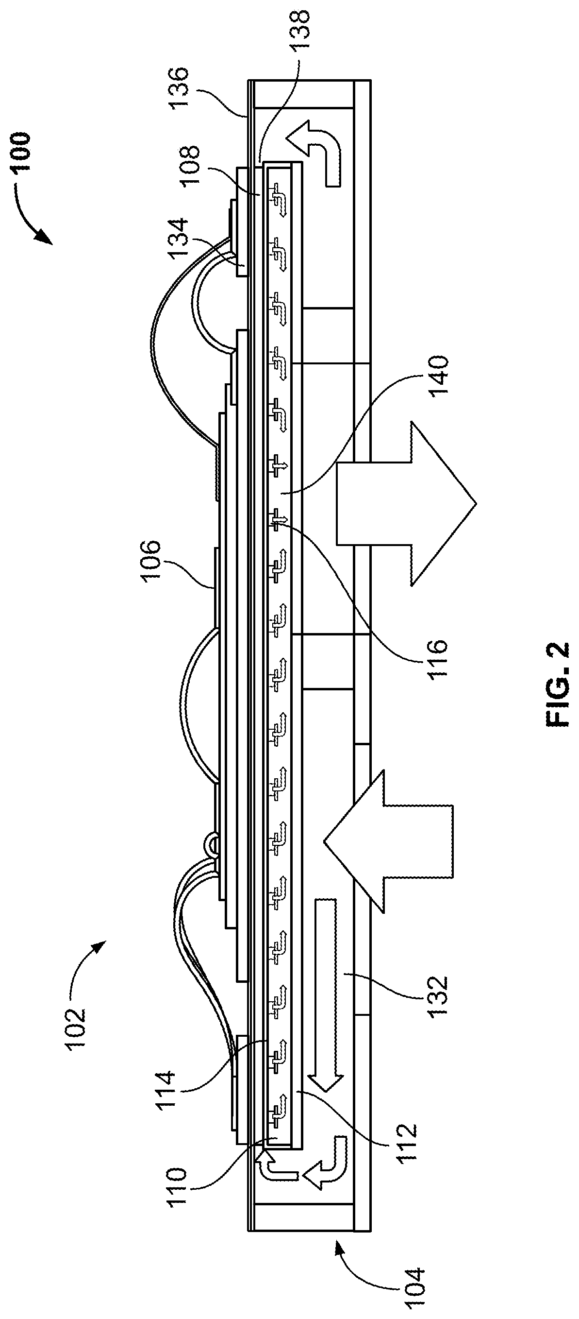
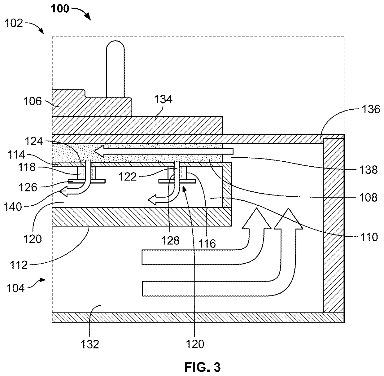
The patent describes a heat exchanger for electronic devices that uses a liquid delivery layer and an evaporation layer with hollow pillars to manage heat. The hollow pillars have an evaporation surface that can hold a droplet of liquid, which is then evaporated through the pore to the evaporation surface. The evaporation surface has a high wetting efficiency and maintains the droplet within a small contact line. The method can efficiently evaporate liquid from the droplet on the hollow pillar, allowing for better thermal management of electronic devices.

Problems solved by technology

However, current thermal management systems have not been completely satisfactory in dissipating the relatively high amounts of heat generated by electronic devices.
Moreover, design aspects of electronic devices such as shape and size are limited at least in part by the capabilities and sizes of the thermal management systems.
Moreover, at least some known systems rely on polar liquids such as water to function and are not compatible with dielectric liquids.

Method used


Image

  • Methods and systems for evaporation of liquid from droplet confined on hollow pillar
  • Methods and systems for evaporation of liquid from droplet confined on hollow pillar
  • Methods and systems for evaporation of liquid from droplet confined on hollow pillar

Examples


example 1

Fluid (VOF) Modeling of Microdroplets on Circular, Square, and Triangular Micropillars

[0123]In various aspects, a Volume of Fluid (VOF) numerical model is used to characterize the evaporation behavior of non-axisymmetrical microdroplets suspended on a hollow micropillar. In one aspect, the VOF model is used to characterize the heat and mass transfer over a non-axisymmetric microdroplet meniscus formed at the outlet of a hollow micropillar. In some aspects, equilibrium profiles and mass transport characteristics of droplets with circular, triangular, and square contact shapes are characterized using the Volume of Fluid (VOF) method. In one aspect, the VOF model is based on a volume of fluid (VOF) multiphase method that accounts for microconvection effects within the droplet and evaporative phase change transport at the liquid-vapor interface, and further provides representation of the vapor diffusion process in the air domain. In an aspect, evaporative mass transport at the liquid-va...

example 2

e Pinning / De-Pinning of Droplet Contact Lines Advancing Along Sharp Edges with Varying Angle and Roundness

[0182]To assess the characteristics of microdroplet pinning and unpinning along sharp substrate edges on a microscale, the following experiments were conducted.

[0183]Geometric edge features 905 with different edge angles and roundness were fabricated using lithography and etching techniques to produce different edge angle and roundness features. Specifically, T-shaped microchannels were fabricated on a plain silicon substrate with acute, right, or obtuse turning angles as shown in FIG. 39. The edge radius of curvature at these sharp edges was varied from ˜100 nm, ˜1 μm to ˜10 μm by changing the photolithography mask and controlling the developing / etching process. In order to achieve the high resolution (<1 μm) to distinguish the different degrees of roundness, laser scanning lithography was used to produce the target feature on the deposited photoresist material. By employing a ...

example 3

let Evaporation from a Hollow Micropillar

[0185]A multiphase flow numerical simulation for observing microdroplet evaporation from a hollow micropillar was demonstrated. Factors in modeling droplets included vapor domain, liquid domain, pressure outlet, vapor diffusion, heat flux wall, axis, and the liquid-solid barrier. Measurements taken included temperature, surface tension, and angular position and observing the triple-phase contact line (TPL) in association to the axis of the micropillar (see FIG. 40). The evaporation rate along the menisci (water) was demonstrated observing the triple-phase contact (TPL) line in association to the axis of the micropillar as well (see FIG. 41). The average transfer coefficient versus the boundary heat flux were calculated (see FIG. 41). It was concluded that the evaporation from thin-film droplet allowed for average heat transfer coefficient exceeding 106 W m−2 K−1 (table below). The highest rate of evaporation was located at the TPL. Models of ...


PUM


Abstract

A heat exchanger for thermal management of an electronic device includes a liquid delivery layer thermally coupled to the electronic device and configured to receive a liquid from a source. The heat exchanger also includes an evaporation layer comprising hollow pillars configured to receive a continuous flow of the liquid from the liquid delivery layer and evaporate the continuous flow of the liquid from droplets maintained on the hollow pillars. Each hollow pillar has an evaporation surface and a pore configured to channel the continuous flow of the liquid through the hollow pillar to the evaporation surface. The evaporation surface being configured to maintain a droplet on the respective hollow pillar within a contact line. The evaporation surface has a wetting efficiency of at least about 95% and the contact line has a length of less than about 0.0314 mm.

Description

CROSS-REFERENCE TO RELATED APPLICATIONS[0001]This application claims priority to U.S. Provisional Application No. 62 / 722,469, filed Aug. 24, 2018, U.S. Provisional Application No. 62 / 826,293, filed Mar. 29, 2019, and U.S. Provisional Application No. 62 / 863,055, filed Jun. 18, 2019, the contents of which are incorporated herein by reference in their entirety.FIELD[0002]The field of the disclosure relates generally to evaporation of liquid. More specifically, the field of the disclosure relates to systems and methods for evaporation of a liquid from a droplet confined on a hollow pillar.BACKGROUND[0003]Current electronic devices include multiple electronic components that are integrated into single assemblies to provide faster signal communication and a tighter footprint than prior devices. Advancements in the integration of electronic components have led to higher generation of heat in confined spaces of the electronic devices. For example, some current electronic devices generate he...

Claims


Application Information

Patent Timeline
Patent Type & Authority Applications(United States)
IPC IPC(8): H01L23/427
CPCH01L23/427H01L23/3735B82Y30/00H05K7/20309H01L2224/4903H01L2224/48472H01L2924/19107H01L25/0655H05K7/20318H05K7/20327
Inventor AGONAFER, DAMENAMA, BINJIANSHAN, LIWEISENSEE, PATRICIAMEACHAM, JOHN MARK
Owner WASHINGTON UNIV IN SAINT LOUIS
Learn More