
Car heat management system and car

A thermal management system and thermal management technology, applied in the field of automotive thermal management, can solve the problems of reduced cruising range, reduced battery life, difficult thermal management and control, etc., and achieve the effects of reducing development costs, improving service life, and increasing cruising range.

Active Publication Date: 2016-10-12
NINGBO GEELY AUTOMOBILE RES & DEV CO LTD
View PDF6 Cites 66 Cited by
  • Summary
  • Abstract
  • Description
  • Claims
  • Application Information

AI Technical Summary

Problems solved by technology

[0004] The existing new energy cooling thermal management system requires multiple controllers or control modules to control each circuit, and finally the vehicle controller performs unified control. Therefore, it is difficult for the existing new energy cooling thermal management system to perform thermal Supervisory control, while separate controllers for increased controllers will result in increased cost per item
[0005] Moreover, the battery cooling management of the new energy cooling thermal management system is only related to the opening and closing of the heat exchange solenoid valve, and has nothing to do with the air conditioning system, that is, the speed of the compressor cannot be controlled according to the temperature of the battery, and the battery can only pass Refrigerant cooling can not dynamically balance the heat load of the air conditioning system in the passenger compartment according to the actual situation; and there is no radiator cooling system in the battery cooling circuit, so the energy saving effect is poor
[0006] In addition, the existing new energy cooling thermal management system does not have a battery heating function. In winter when the temperature is low, the cruising range of new energy vehicles that use batteries to provide kinetic energy is reduced, and the service life of the battery is also reduced.

Method used


Image

  • Car heat management system and car
  • Car heat management system and car
  • Car heat management system and car

Examples


Embodiment Construction

[0030]In order to further explain the technical means and effects that the present invention adopts to achieve the intended purpose of the invention, the specific implementation, structure, characteristics and features of the automobile thermal management system and automobile proposed according to the present invention will be described below in conjunction with the accompanying drawings and preferred embodiments. Its functions are detailed as follows:

[0031] The aforementioned and other technical contents, features and effects of the present invention will be clearly presented in the following detailed description of preferred embodiments with reference to the drawings. Through the description of specific implementation methods, the technical means and effects of the present invention to achieve the intended purpose can be understood more deeply and specifically, but the attached drawings are only for reference and description, and are not used to explain the present invent...


PUM


Abstract

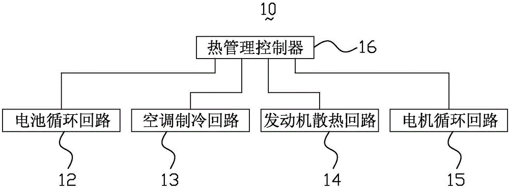
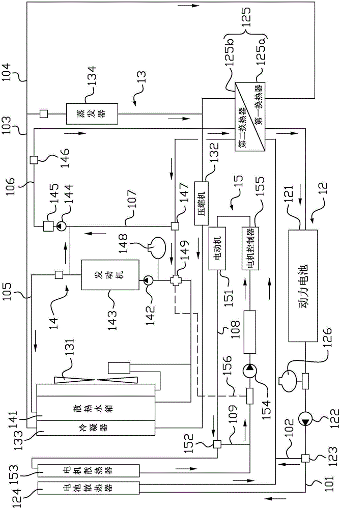
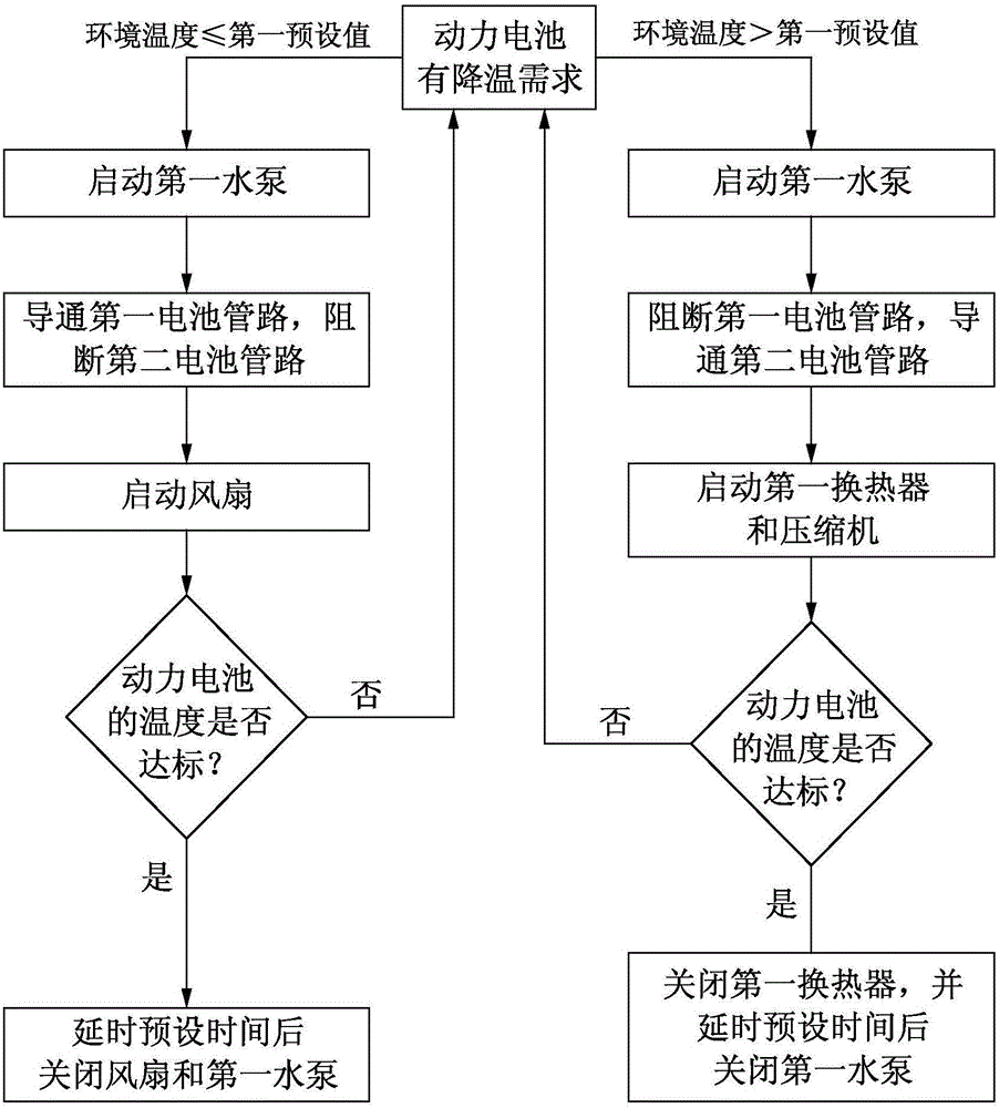
A car heat management system comprises a battery circulating loop, an air conditioner refrigeration loop and a heat management controller, the battery circulating loop comprises a first battery pipeline, a power battery, a battery heat radiator and a heat exchange assembly, and the power battery, the battery heat radiator and the heat exchange assembly are connected to the first battery pipeline. The heat exchange assembly is used for carrying out heat exchange between the battery circulating loop and an external loop. The air conditioner refrigeration loop comprises a first refrigeration pipeline, a second refrigeration pipeline, a fan, a compressor, a condenser and an evaporator, and the compressor, the condenser and the evaporator are connected to the first refrigeration pipeline. The second refrigeration pipeline is connected with the heat exchange assembly, the two ends of the second refrigeration pipeline are connected to the positions, at the two ends of the evaporator, of the first refrigeration pipeline, and the condenser and the battery heat radiator are arranged on the air outlet side of the fan. The heat management controller is used for selectively starting the fan or the compressor to cool the power battery according to the cooling need of the power battery and the environment temperature. The car heat management system is correlated and integrated with a car air conditioning system, the heat load of the air conditioning system can be balanced, and the energy saving effect is good. The invention further relates to a car.

Description

technical field [0001] The invention relates to the technical field of automobile heat management, in particular to an automobile heat management system and an automobile. Background technique [0002] With the limitation of air pollution control and national fuel consumption targets, new energy vehicles have attracted more and more attention from the market and enterprises. The cooling thermal management requirements of the new power system motors and batteries are directly related to their power and economy. [0003] The control of the existing new energy cooling thermal management system mainly adopts separate control; for example, when the temperature of the battery is too high and needs to be cooled, the battery controller BMS controls the start of the water pump in the battery cooling circuit, and then the air conditioner controller controls the start of the heat exchange electromagnetic valve (chiller), which enables the refrigerant in the air conditioning system to e...

Claims


Application Information

Patent Timeline
Patent Type & Authority Applications(China)
IPC IPC(8): B60H1/00B60H1/03B60K11/04B60K11/06H01M10/613H01M10/615H01M10/625H01M10/6567H01M10/663
CPCB60H1/00278B60H1/004B60H1/00642B60H1/034B60K11/04B60K11/06H01M10/613H01M10/615H01M10/625H01M10/6567H01M10/663Y02E60/10Y02T10/88
Inventor 赵家威
Owner NINGBO GEELY AUTOMOBILE RES & DEV CO LTD
Learn More