Vital-sign radar sensor using a wireless frequency-locked loop
- Summary
- Abstract
- Description
- Claims
- Application Information
AI Technical Summary
Benefits of technology
Problems solved by technology
Method used
Image
Examples
first embodiment
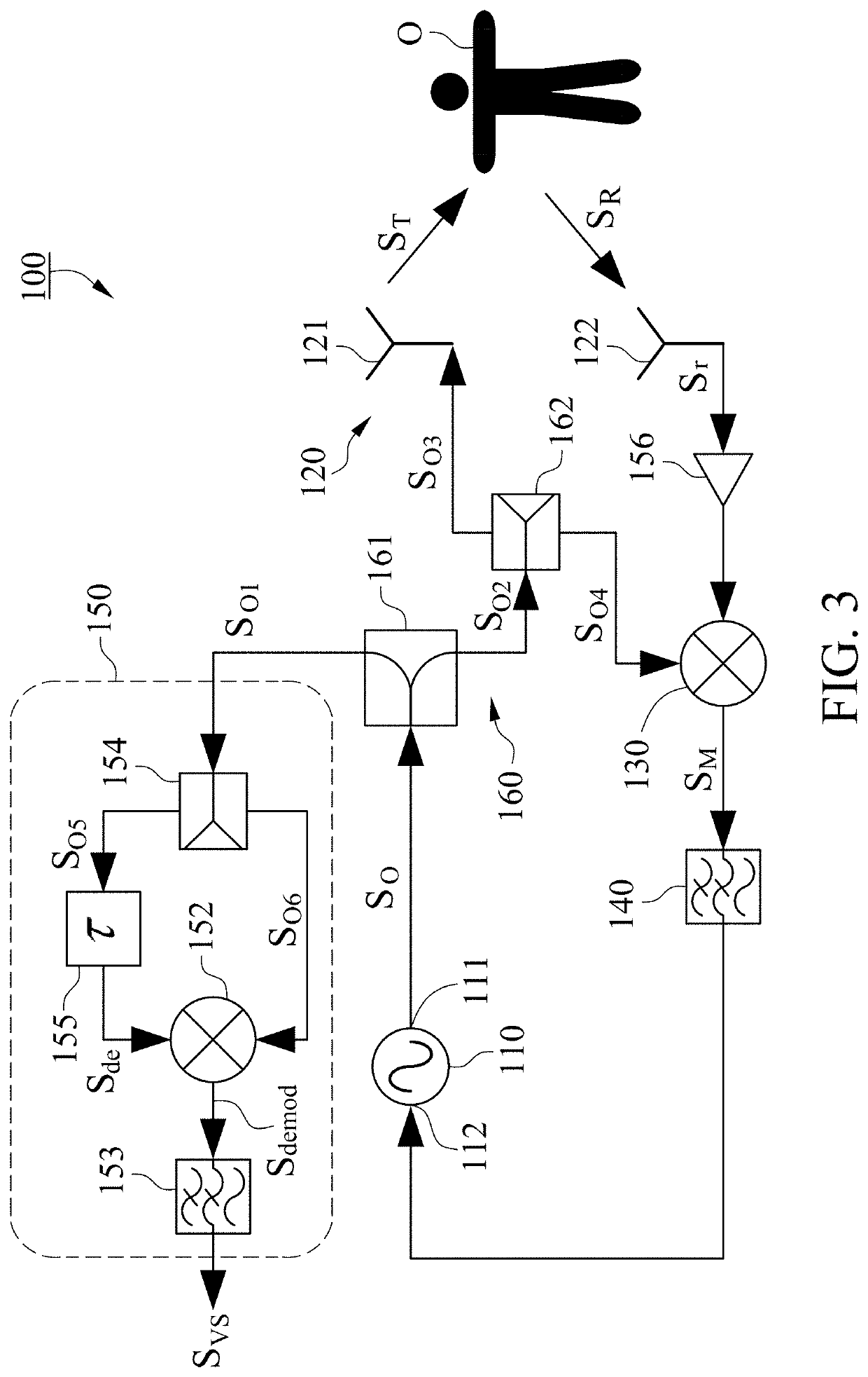
[0011]With reference to FIG. 1, a vital-sign radar sensor 100 in accordance with the present invention includes a voltage-control oscillator (VCO) 110, an antenna component 120, a mixer 130, a loop filter 140 and a frequency demodulation component 150.
[0012]The VCO 110 includes an output port 111 and a tuning port 112 and is configured to output an oscillation signal SO from the output port 111. The antenna component 120 includes a transmit antenna 121 and a receive antenna 122, the transmit antenna 121 is coupled to the output port 111 of the VCO 110 and configured to receive and transmit the oscillation signal SO as a transmitted signal ST to a subject O. While the subject O has a motion relative to the transmit antenna 121, the motion results in a Doppler Effect on the transmitted signal ST to allow a reflected signal SR from the subject O to contain Doppler phase shifts. The receive antenna 122 is configured to receive the reflected signal SR as a received signal Sr from the sub...
second embodiment
[0020]With reference to FIG. 2 again, the frequency demodulation component 150 further includes a power splitter 154 in the The power splitter 154 is coupled to the first power splitter 161 and configured to receive and divide the oscillation signal SO1 into two paths, the oscillation signal SO5 in one path is delivered to the SAW filter 151, and the oscillation signal SO6 in the other path is delivered to the demodulation mixer 152. In a similar way, the phase noise of the VCO 110 is also reduced by the wireless FLL to improve the vital-sign sensitivity of the vital-sign radar sensor 100.
[0021]In a third embodiment of the present invention as shown in FIG. 3, the SAW filter 151 of the frequency demodulation component 150 is replaced by a delay line 155 and the ILO 170 is replaced by a low noise amplifier (LNA) 180. The delay line 155 is coupled to the VCO 110 via the power splitter 154 and the first power splitter 161 for receiving the oscillation signal SO5 and configured to outp...
fourth embodiment
[0022]FIG. 4 shows the present invention, multiple vital-sign radar sensors 100 are provided to detect vital sign(s) of one subject O or multiple subjects O. A signal processor 200 is electrically connected to the vital-sign radar sensors 100 and configured to control the phase difference between the transmitted signals ST output from the vital-sign radar sensors 100 so as to form a beam which is available with angle adjustment to detect the subjects O located at different orientations. The signal processor 200 is also configured to receive the vital-sign signals SVS from the vital-sign radar sensors 100, the vital-sign signals SVS detected by the vital-sign radar sensors 100 present the vital sign of the subject O when the beam composed of the transmitted signals ST is directed toward the subject O, consequently, the orientation of the subject O can be determined.
[0023]The present invention utilizes the wireless FLL composed of the VCO 110, the antenna component 120, the propagatio...
PUM
 Abstract
Description
Claims
Application Information
 - R&D
- Intellectual Property
- Life Sciences
- Materials
- Tech Scout
- Unparalleled Data Quality
- Higher Quality Content
- 60% Fewer Hallucinations
Browse by: Latest US Patents, China's latest patents, Technical Efficacy Thesaurus, Application Domain, Technology Topic, Popular Technical Reports.
© 2025 PatSnap. All rights reserved.Legal|Privacy policy|Modern Slavery Act Transparency Statement|Sitemap|About US| Contact US: help@patsnap.com


