Guide roller and transport device comprising several rollers

a technology of guide rollers and transport devices, which is applied in the field of rollers, can solve the problems of premature wear of rollers, slow correction of sheet position, and clogging of sheets, and achieve the effect of releasing excessive mechanical stresses and improving lateral flexibility

Active Publication Date: 2021-09-23
BOBST MEX SA
View PDF0 Cites 0 Cited by
  • Summary
  • Abstract
  • Description
  • Claims
  • Application Information

AI Technical Summary

Benefits of technology

[0027]According to another embodiment, the roller with its cuts may comprise least two disks. Thus, a roller divided into multiple disks provides even better lateral flexibility. Indeed, the disks meet at the cuts and define, on the roller, one or more elastically deformable segments which can flex independently in the axial direction.
[0028]Such a roller with disks has lateral flexibility, each disk flexing independently of one another. Thus, this independence in the flexing of the disks with respect to one another makes it possible to release excessive mechanical stresses once an elastically deformable disk segment located between two cuts is no longer in contact with the sheet. A roller with disks makes it possible to convey and align the sheet independently of the starting position of the sheet.

Problems solved by technology

However, when the jogging angle is small, correction of the position of the sheet is very slow.
Conversely, when the jogging angle is large, the sheet is aligned more rapidly, but large mechanical stresses are generated when the sheet is pressed against the end stop, which can cause crumpling of the sheet or premature wear of the roller.

Method used


Image

  • Guide roller and transport device comprising several rollers
  • Guide roller and transport device comprising several rollers
  • Guide roller and transport device comprising several rollers

Examples


second embodiment

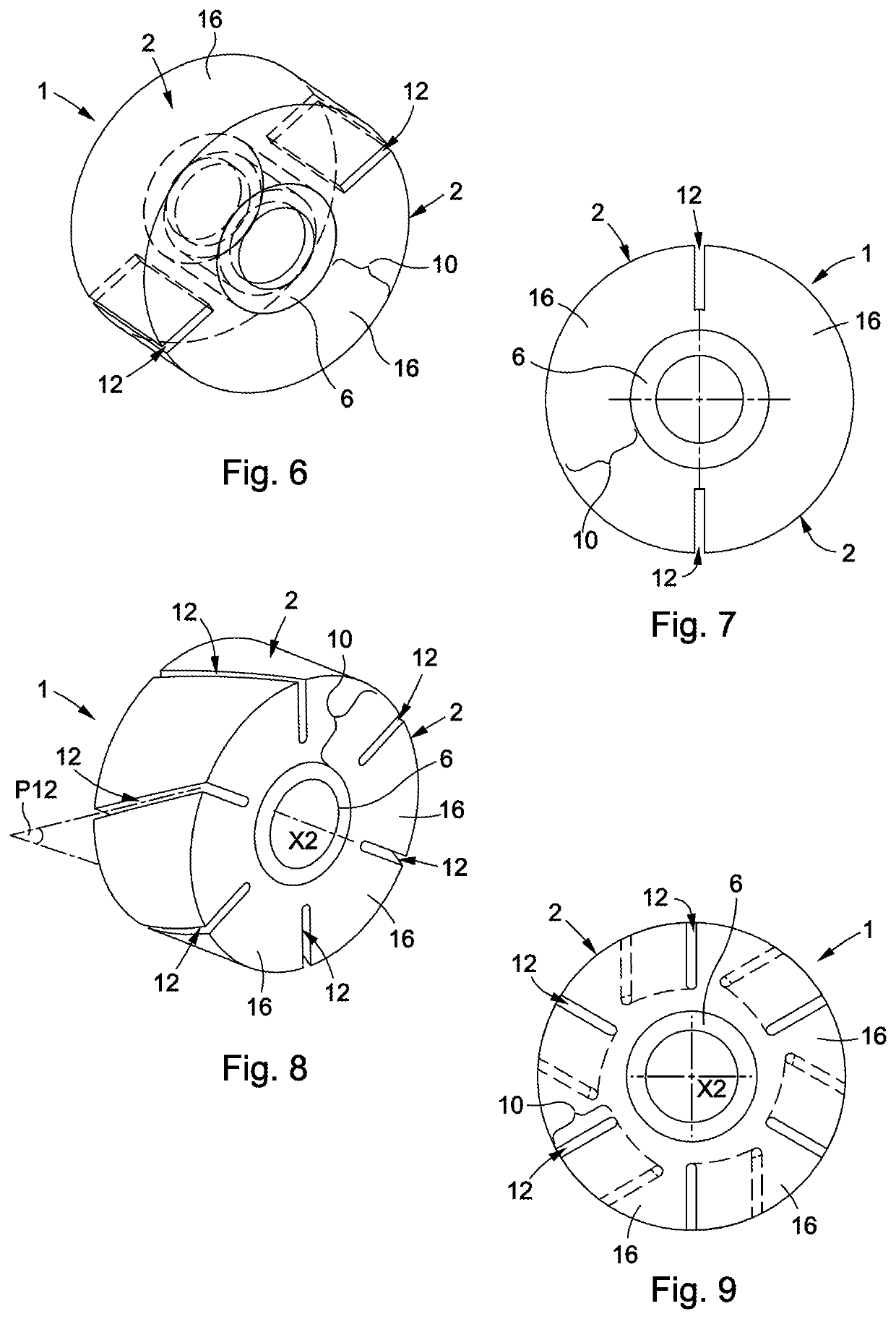
[0064]FIGS. 6 and 7 illustrate a roller 1 according to a Insofar as the roller 1 of FIGS. 6 and 7 is similar to the roller 1 of FIG. 1, the description of the roller 1 provided hereinabove in relation to FIG. 1 can be transposed to the roller 1 of FIGS. 6 and 7, with the exception of the notable differences mentioned hereinbelow. The roller 1 of FIGS. 6 and 7 differs from the roller 1 of FIG. 1 in that the deformation portion 10 has two cuts 12, instead of six, which extend from the contact surface 2 to the central portion 6. Furthermore, the roller 1 of FIGS. 6 and 7 differs from the roller 1 of FIG. 1 in that the deformation portion 10 has no cutouts. Quite the opposite: the deformation portion 10 is solid. However, as in the example of FIG. 1, the deformation portion 10 is configured to deform elastically when the roller 1 guides the sheet 101 by friction.

third embodiment

[0065]FIGS. 8 and 9 illustrate a roller 1 according to a Insofar as the roller 1 of FIGS. 8 and 9 is similar to the roller 1 of FIG. 1, the description of the roller 1 provided hereinabove in relation to FIG. 1 can be transposed to the roller 1 of FIGS. 8 and 9, with the exception of the notable differences mentioned hereinbelow. The roller 1 of FIGS. 8 and 9 differs from the roller 1 of FIG. 1 in that each cut 12 is configured such that the intersection of this cut 12 with the contact surface 2 forms a segment that is oblique to the axis of revolution X2 of the contact surface 2. As shown in FIG. 8, each cut 12 extends parallel to a plane P12 which includes the oblique segment.

fourth embodiment

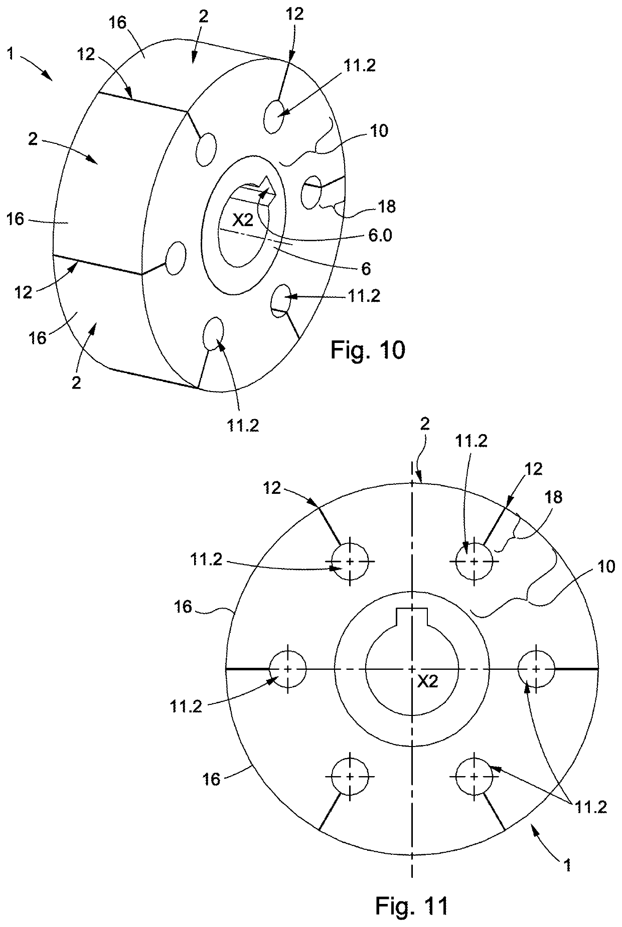
[0066]FIGS. 10 and 11 illustrate a roller 1 according to a Insofar as the roller 1 of FIGS. 10 and 11 is similar to the roller 1 of FIG. 1, the description of the roller 1 provided hereinabove in relation to FIG. 1 can be transposed to the roller 1 of FIGS. 10 and 11, with the exception of the notable differences mentioned hereinbelow. The roller 1 of FIGS. 10 and 11 differs from the roller 1 of FIG. 1 in that each cutout 11.2 has a rounded shape, in order to reduce mechanical stresses. Each cutout 11.2 has the overall shape of a cylinder extending parallel to an axial direction X2 of the roller 1. Furthermore, the central portion 6 has a slot 6.0 that is configured to receive a key (not shown). The slot 6.0 extends parallel to the axial direction X2.


PUM


Abstract

A roller for guiding a sheet (101) by friction has a contact surface (2) designed to be in contact with the sheet (101), the contact surface (2) having, overall, a shape of revolution when the roller (1) is at rest, a central portion (6) configured to mechanically connect the roller (1) to a rotating drive element, and a deformation portion (10) located between the contact surface (2) and the central portion (6), the deformation portion (10) being configured to deform elastically when the roller (1) guides the sheet (101) by friction.
The deformation portion (10) comprises at least one cut (12) extending from the contact surface (2) to the central portion (6), the cut (12) being arranged such that the deformation portion (10) comprises at least one elastically deformable segment (16).

Description

[0001]The present invention relates to a roller for guiding a sheet by friction. The present invention further relates to a conveying device comprising such rollers for conveying sheets by friction.[0002]The present invention can for example be applied to the field of making foldable boxes from sheets of cardboard, wherein the roller then serves to guide each sheet of cardboard. A foldable box can for example be a packaging carton. In general, such sheets of cardboard are moved along a production line. In addition, the present invention can find application in other fields requiring the alignment of objects in sheet form such as sheet metal, wooden boards, slabs of plastic material, etc.PRIOR ART[0003]EP1837298 describes a conveying device comprising multiple rollers for pushing sheets by friction. Each roller has i) an outer surface for contact with the sheet, ii) a central bore for rotation of the roller, and iii) an elastically deformable portion located between the outer contact...

Claims


Application Information

Patent Timeline
Patent Type & Authority Applications(United States)
IPC IPC(8): B65H27/00B31B50/04
CPCB65H27/00B31B50/042B65H2701/176B65H2404/117B65H2404/1321B65H2404/11221B65H2404/1122B65H2404/1314B65H2701/1762B31B50/046B65H9/166
Inventor HORNICK, PAULPILLONEL, GILLES
Owner BOBST MEX SA
Why Eureka
Try Eureka