
Method for manufacturing nitride semiconductor laminate, nitride semiconductor laminate, method for inspecting film quality, and method for inspecting semiconductor growing device

a technology of semiconductor laminates and growing devices, applied in the field of methods, can solve problems such as the difficulty of properly inspecting the physical properties of homoepitaxial films containing crystals

Pending Publication Date: 2021-07-15
SUMITOMO CHEM CO LTD
View PDF0 Cites 1 Cited by
  • Summary
  • Abstract
  • Description
  • Claims
  • Application Information

AI Technical Summary

Benefits of technology

The present invention provides a new way to inspect the quality of films made from group III nitride semiconductor crystals without damaging them and without touching them.

Problems solved by technology

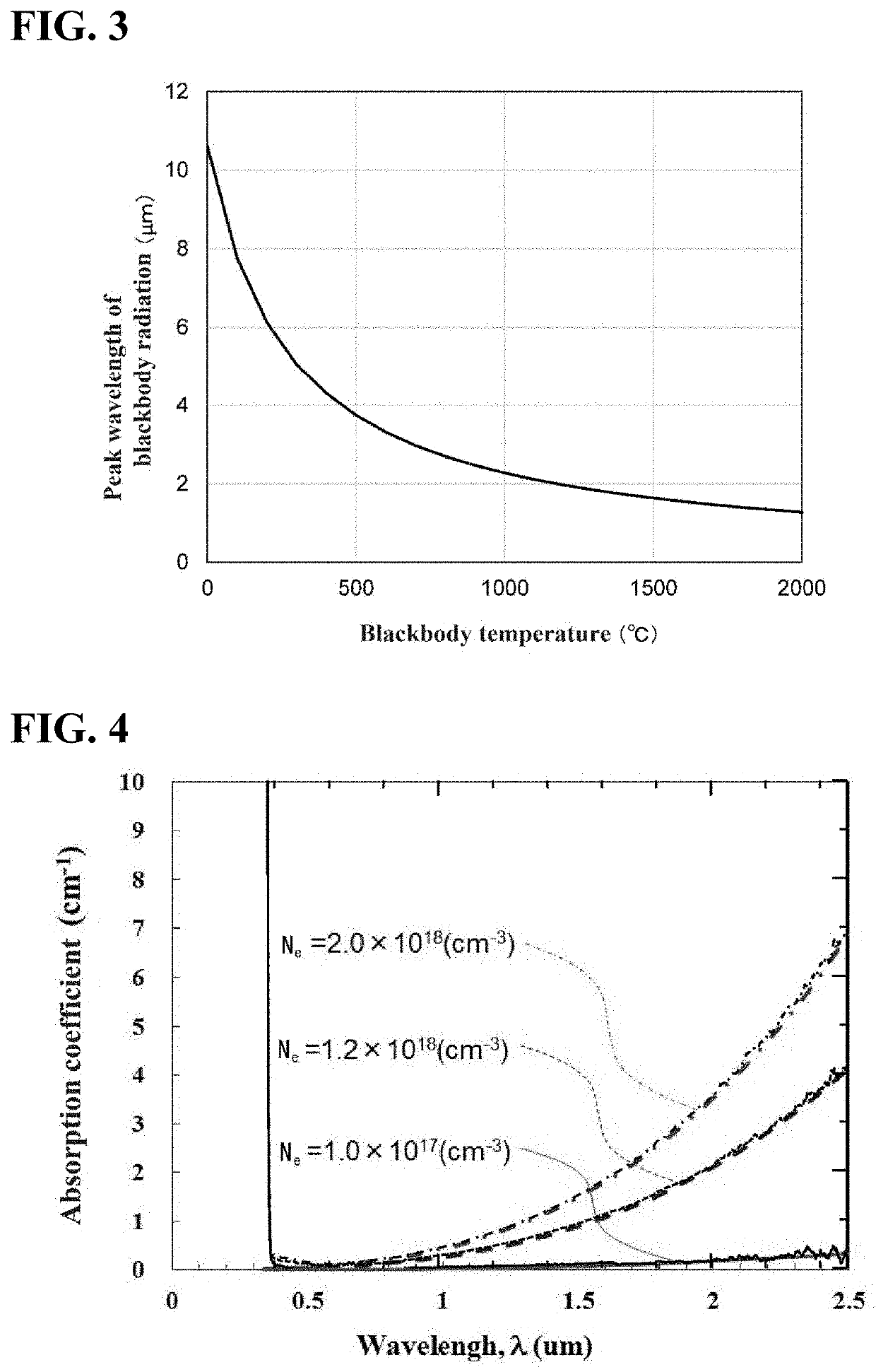
However, regarding crystals of group III nitride semiconductors represented by gallium nitride (GaN), it has been difficult to properly inspect physical properties of a homoepitaxial film comprising crystals having the same composition as the composition of the substrate, for example using the FT-IR method, because an influence of dislocation scattering is large, and there is no difference in an absorption coefficient in an infrared region (IR), especially at low carrier concentration of 1×1017 cm−3 or less.

Method used


Image

  • Method for manufacturing nitride semiconductor laminate, nitride semiconductor laminate, method for inspecting film quality, and method for inspecting semiconductor growing device
  • Method for manufacturing nitride semiconductor laminate, nitride semiconductor laminate, method for inspecting film quality, and method for inspecting semiconductor growing device
  • Method for manufacturing nitride semiconductor laminate, nitride semiconductor laminate, method for inspecting film quality, and method for inspecting semiconductor growing device

Examples


first embodiment

[0062]Hereinafter, a first embodiment of the present invention will be described with reference to the drawings.

[0063]The nitride semiconductor laminate 1 described by way of example in this embodiment is, for example, a substrate-like structure used as a substrate when producing a semiconductor device as a Schottky barrier diode (SBD). Since it is used as a substrate for a semiconductor device, the nitride semiconductor laminate 1 may be hereinafter referred to as an “intermediate body” or an “intermediate precursor”.

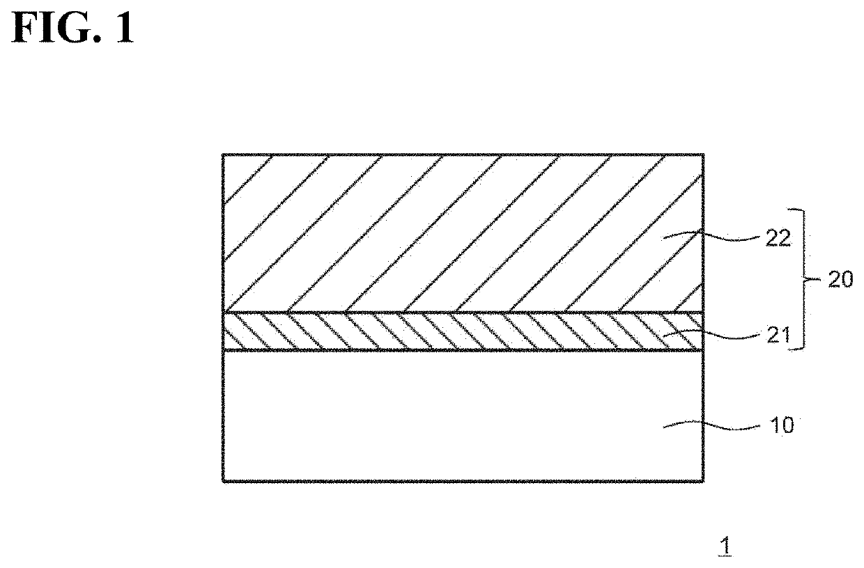
[0064]As illustrated in FIG. 1, the nitride semiconductor laminate (intermediate body) 1 according to the present embodiment is configured to include at least a substrate 10 and a semiconductor layer 20 which is a thin film formed on the substrate 10.

(1-i) Detailed configuration of the substrate 10

[0065]Subsequently, the substrate 10 constituting the nitride semiconductor laminate (intermediate body) 1 will be described in detail. Note that in the following, a main sur...

second embodiment

[0293]Next, a second embodiment of the present invention will be described.

(1) Method for Producing Nitride Semiconductor Laminate 1

[0294]in the second embodiment, a method for producing the nitride semiconductor laminate 1 is different from that of the first embodiment. Specifically, the film thickness measurement step (S130) is different from that of the first embodiment, and the substrate production step (S110) and the semiconductor layer growth step (S120) are the same as those of the first embodiment (see FIG. 7). The configuration of the nitride semiconductor laminate 1 in the second embodiment is the same as that in the first embodiment (see FIG. 1). That is, also in the second embodiment, the nitride semiconductor laminate 1 is configured to enable the measurement of the film thickness using the FT-IR method. Hereinafter, the film thickness measurement step (S130) according to the second embodiment will be described.

[0295]In the film thickness measurement step (S130) of the ...

third embodiment

[0331]Next, a third embodiment will be described. In the third embodiment, a method for producing a nitride semiconductor laminate 2 including a semiconductor layer 40 configured as a multilayer film having multiple layers (two or more layers, for example, five layers) on a substrate 30 will be described. The method for producing the nitride semiconductor laminate 2 according to the third embodiment can be applied as an inspection method for a semiconductor growth apparatus, as will be described in detail later.

[0332]FIG. 20 is a cross-sectional view schematically illustrating a schematic configuration example of the nitride semiconductor laminate 2. The semiconductor layer 40 is homoepitaxially grown on the substrate 30, and has, for example, five layers 41 to 45.

[0333]FIG. 21 is a flow chart illustrating a method for producing the nitride semiconductor laminate 2. The method for producing the nitride semiconductor laminate 2 includes a substrate preparation step (S310), a semicond...


PUM

PropertyMeasurementUnit
intensity reflectanceaaaaaaaaaa
wavenumberaaaaaaaaaa

Abstract

There is provided a method for producing a nitride semiconductor laminate in which a thin film is homoepitaxially grown on a substrate comprising group III nitride semiconductor crystals, the method including: homoepitaxially growing a thin film on a substrate, using the substrate in which a dislocation density on its main surface is 5×10⁶ pieces / cm2 or less, a concentration of oxygen therein is less than 1×10¹⁷ at·cm−3, and a concentration of impurities therein other than n-type impurity is less than 1×10¹⁷ at·cm−3; and inspecting a film quality of the thin film formed on the substrate, wherein in the inspection of the film quality, the film quality of the thin film is inspected by detecting a deviation of an amount of reflected light at a predetermined wavenumber determined in a range of 1,600 cm−1 or more and 1,700 cm−1 or less in a reflection spectrum obtained by irradiating the thin film on the substrate with infrared light, from an amount of reflected. light at the predetermined wavenumber determined according to a film thickness of the thin film, a carder concentration of the substrate, and a carrier concentration of the thin film.

Description

BACKGROUNDTechnical Field[0001]The present invention relates to a method for producing a nitride semiconductor laminate, a silicon semiconductor product, a method for inspecting a film quality, and a method for inspecting a semiconductor growth device.Description of Related Art[0002]As a non-contact and non-destructive method for inspecting physical properties of a thin film of semiconductor crystals grown on a substrate, for example, Fourier transform infrared spectroscopy (FT-IR. method) is known (see, for example, Patent Document 1).[0003]Patent Document 1: Japanese Unexamined Patent Publication No. 1992-120404[0004]However, regarding crystals of group III nitride semiconductors represented by gallium nitride (GaN), it has been difficult to properly inspect physical properties of a homoepitaxial film comprising crystals having the same composition as the composition of the substrate, for example using the FT-IR method, because an influence of dislocation scattering is large, and ...

Claims


Application Information

Patent Timeline
Patent Type & Authority Applications(United States)
IPC IPC(8): G01N21/95H01L29/20G01N21/59G01N21/3563G01N21/359H01L21/66H01L21/02
CPCG01N21/9501H01L29/2003G01N21/59G01N2021/3568G01N21/359H01L22/12H01L21/0254G01N21/3563G01B11/06G01N2021/3595H01L21/02576H01L21/0262H01L21/02389G01N21/8422C30B25/16C30B29/406
Inventor HORIKIRI, FUMIMASA
Owner SUMITOMO CHEM CO LTD
Learn More