
Apparatus for catalytic decomposition of nitrous oxide in a gas stream

a technology of nitrous oxide and apparatus, which is applied in the direction of respirators, other chemical processes, separation processes, etc., can solve the problems of nitrous oxide, problems such as affecting the health of such personnel, and causing problems

Active Publication Date: 2021-05-20
MEDCLAIR AB
View PDF0 Cites 0 Cited by
  • Summary
  • Abstract
  • Description
  • Claims
  • Application Information

AI Technical Summary

Benefits of technology

The invention is a device that breaks down nitrous oxide gas released from patients during pain relief treatments. The device ensures that only the nitrous oxide gas is stored, which prevents the need to constantly heat the gas as it passes through the device and reduces the concentration of nitrous oxide gas released into the environment. This helps to maintain safe and effective treatments while minimizing the risk of injury or damage to the environment.

Problems solved by technology

Nitrous oxide exposition over a long period of time, however, can be harmful to such personnel even at very low concentrations in case of frequent exposition over many years.
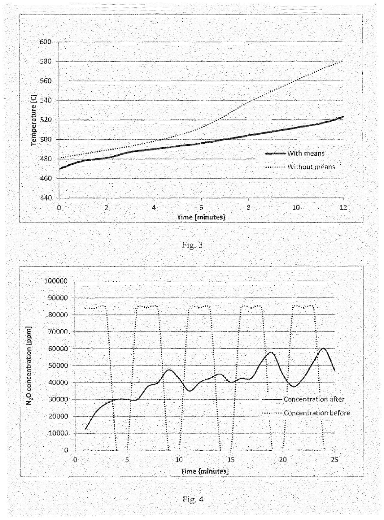
The reaction is strongly exothermic, and at concentrations of nitrous oxide higher than about 1-2% problems may occur.
Should the nitrous oxide to be dealt with have a high concentration this implies problems with its destruction at a health care unit.
During periods of high concentrations, the catalytic decomposition unit has increased risks of a) overheating and explosion due to an uncontrolled acceleration of the temperature, and b) formation of undesired levels of harmful by-products, such as NOx.
The irregular switches between high and zero concentration of nitrous oxide further complicate the situation since this will mean uncontrolled switches in outcome of the reaction (products / by-products), reaction rate, concentrations, temperature etc.
A further problem with catalytic decomposition of nitrous oxide is that, in case high concentrations of nitrous oxide is feed to the decomposition reactor, the temperature of the decomposition reactor may be too high which may destroy the catalyst of the decomposition reactor.
At these concentrations, local hot spots (local high temperature rise) can occur in the catalyst which can be destructive.

Method used


Image

  • Apparatus for catalytic decomposition of nitrous oxide in a gas stream
  • Apparatus for catalytic decomposition of nitrous oxide in a gas stream
  • Apparatus for catalytic decomposition of nitrous oxide in a gas stream

Examples


Embodiment Construction

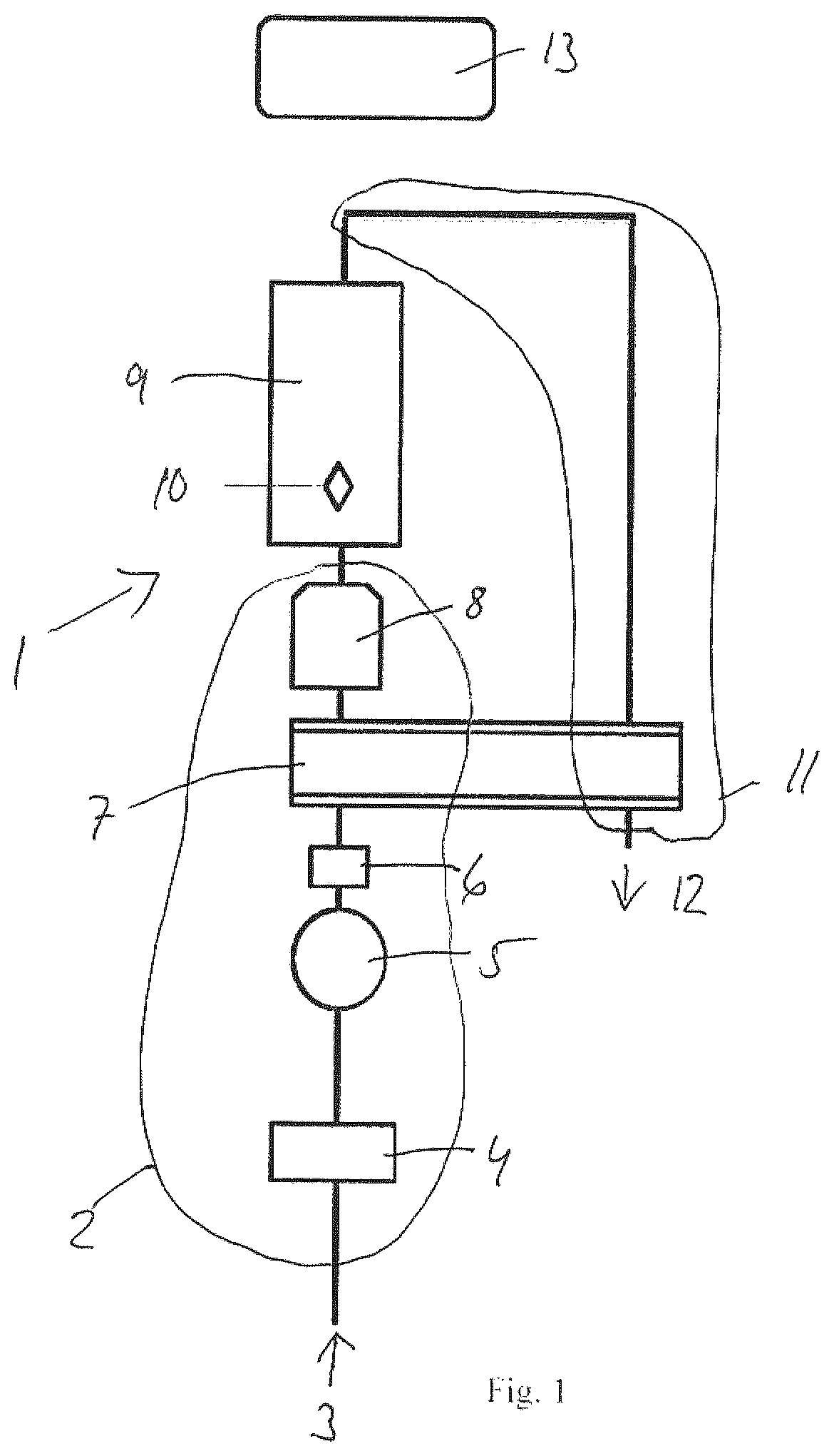
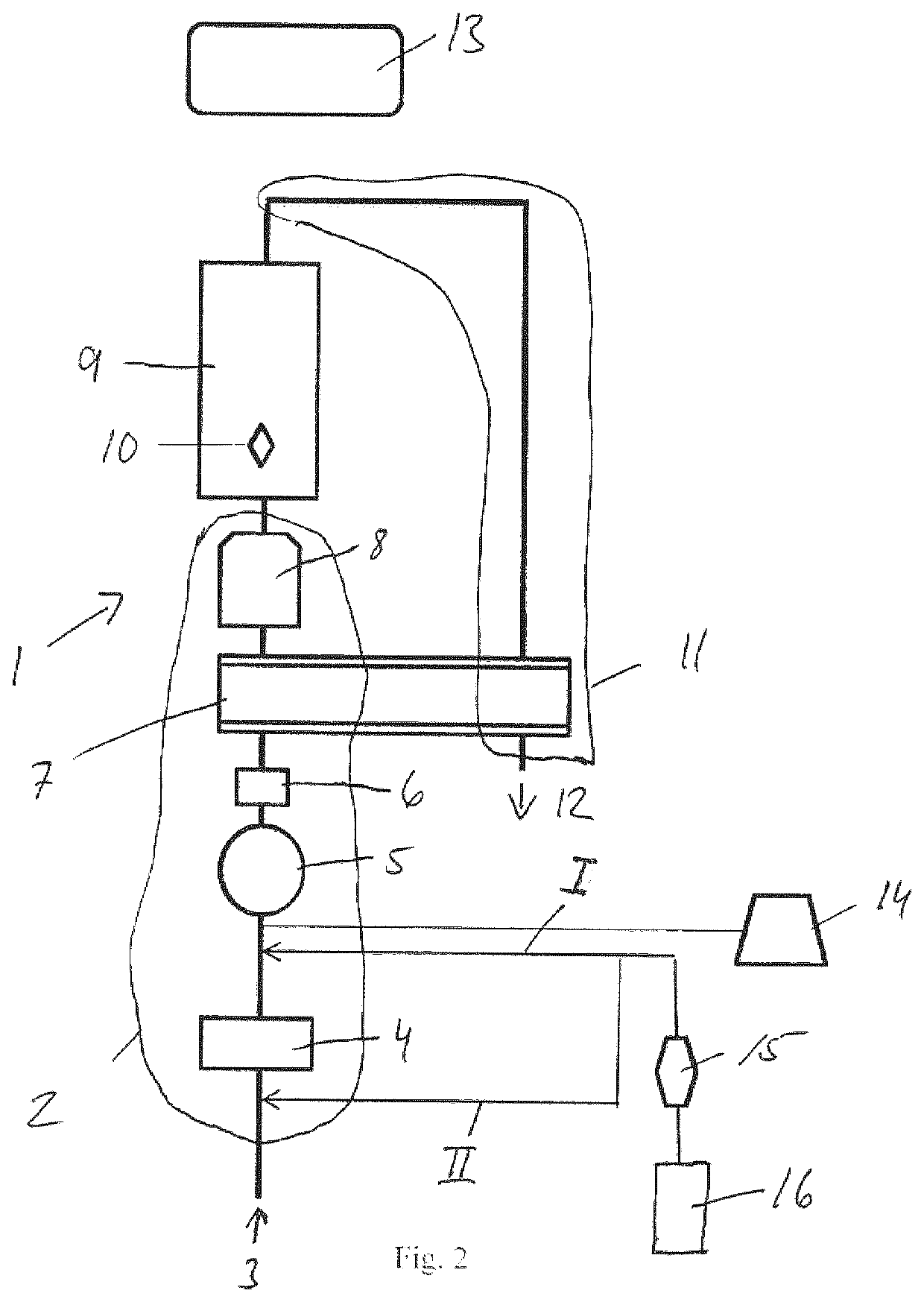
[0028]FIG. 1 show a schematic view of an apparatus 1 for catalytic decomposition of nitrous oxide contained in a gas mixture exhaled by a patient, the apparatus 1 preferably being in the form of a mobile unit to be used close to at least one patient receiving pain relief.

[0029]Said apparatus 1 comprises, as seen in the flow direction of the gas mixture to be treated, an inlet arrangement 2 comprising a gas inlet 3 for an inlet gas being a mixture of oxygen containing gas and nitrous oxide, at least one adsorption / desorption means 4 for selective adsorption / desorption of nitrous oxide, a fan 5, a flow meter 6, a heat exchanger 7, and a heater 8. The apparatus 1 further comprises a nitrous oxide decomposition reactor 9 provided with at least one temperature sensor 10, an outlet arrangement 11 comprising at least a gas outlet 12, and a control unit 13 for controlling and monitoring the temperature and gas flow in the nitrous oxide decomposition reactor and possibly for heating the adso...


PUM

PropertyMeasurementUnit
Temperatureaaaaaaaaaa
Concentrationaaaaaaaaaa
Surface areaaaaaaaaaaa

Abstract

The invention relates to an apparatus (1) for catalytic decomposition of nitrous oxide in a gas stream derived from exhalation air from a patient. The apparatus (1) comprises an inlet arrangement (2) with a gas inlet (3) for the exhalation air, an outlet arrangement (11) with a gas outlet (12) for an outlet gas, and between these arrangements a through-flow decomposition chamber (9) containing a catalyst material. According to the invention the apparatus is provided with a nitrous oxide adsorption / desorption means (4) in the inlet arrangement (2) for level out variations in the concentration of nitrous oxide fed to the decomposition chamber (9).

Description

FIELD OF THE INVENTION[0001]The present invention relates to an apparatus for catalytic decomposition of nitrous oxide in a gas stream derived from exhalation air from a patient according to the preamble of claim 1.BACKGROUND OF THE INVENTION[0002]Mixtures of nitrous oxide (N2O) and oxygen (O2) are widely used in medicine for pain relief.[0003]Within health care units, nitrous oxide is used within surgery, dental care, maternity care during delivery etc. due to its anaesthetic and analgesic effects on patients. The typical patient is allowed to inhale a gas mixture (inhalation air) in which the main components are nitrous oxide, typically in concentrations ≥10%, such as ≥20% and / or ≤80%, such as ≤70% (v / v) and oxygen.[0004]The composition of the air exhaled by a patient receiving nitrous oxide is essentially the same as the composition of the inhaled air except that there typically are increases in moisture content (water) and carbon dioxide. Exhaled air from patients inhaling nitro...

Claims


Application Information

Patent Timeline
IPC IPC(8): A61M16/00B01D53/86B01D53/04B01J20/20B01J20/18B01J20/28
CPCA61M16/0093A61M2202/0283B01D53/8696B01D53/0438B01J20/20B01J20/18B01J20/28064B01J20/28066B01D2259/40088B01D2253/102B01D2253/306B01D2257/402B01D2259/4533B01D2259/455B01D2255/1023B01D53/8631B01D53/04B01D53/869Y02C20/10A61M16/00B01D53/8625Y02P20/30
Inventor SZABÓ, ISTVÁNSUNDLING, JERKERNYBERG, TOMAS
Owner MEDCLAIR AB
Learn More