Battery cooling system for new energy vehicle

a technology for new energy vehicles and cooling systems, which is applied in the direction of battery/fuel cell control arrangement, secondary cell servicing/maintenance, cell components, etc., can solve the problem of achieve quick dissipation of heat in batteries, accelerate the heat dissipation speed of batteries, and reduce the load of batteries

Active Publication Date: 2021-04-08
ZHU GONG
View PDF0 Cites 6 Cited by
  • Summary
  • Abstract
  • Description
  • Claims
  • Application Information

AI Technical Summary

Benefits of technology

The patent is about a device that helps cool down batteries in electric vehicles. It uses a thermal expansion liquid and a sliding plug to absorb and dissipate the heat emitted by the battery. The device is driven by the heat from the battery, which helps keep the battery cool and reduce the load on it. The device can adjust its heat dissipation capacity based on the vehicle's operating conditions. The device has high-speed airflow generated when the vehicle is driving, which helps cool down the battery. Additionally, the patent suggests setting air inlet holes at the lower end of a shield box to improve the protection and heat dissipation performance of the battery. Overall, the device helps improve the battery's performance and lifespan.

Problems solved by technology

Different heating conditions of chambers on both sides of a cylinder cause a sliding plug to move up and down, which in turn pushes a coolant in a condenser pipe to flow, thereby quickly dissipating heat in a battery.

Method used


Image

  • Battery cooling system for new energy vehicle
  • Battery cooling system for new energy vehicle
  • Battery cooling system for new energy vehicle

Examples


embodiment 1

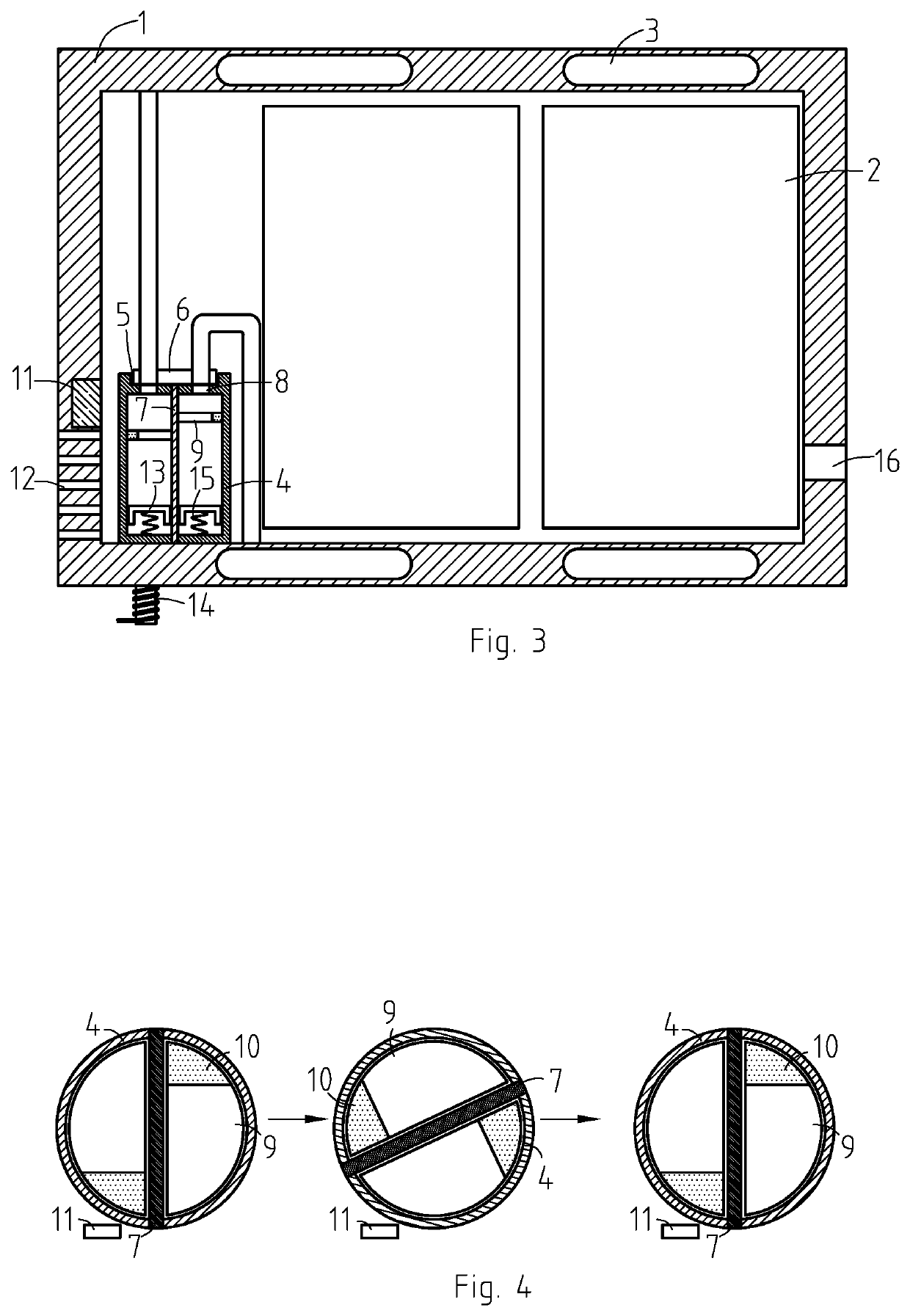
[0025]Referring to FIGS. 1-2, a battery cooling system for new energy vehicle comprises a shield boxes 1 with a plurality of batteries 2 installed inside, an inner wall of the shield box 1 is provided with a condenser pipe 3 filled with coolant, it should be noted that the condenser pipe 3 is distributed in a serpentine shape on the inner wall of the shield box 1 to increase contact area with the battery 2, so as to efficiently dissipate heat. A cylinder 4 rotatably connects with an inner bottom of the shield box 1, an upper end of the cylinder 4 is provided with a circular groove 5 arranged coaxially with the cylinder 4, the circular groove 5 is sealed and rotated to connect with a circular block 6, a water inlet end and a water outlet end of the condenser pipe 3 are both sealed and penetrated through the circular block 6. A heat insulation plate 7 is arranged in the cylinder 4, it should be noted that the heat insulation plate 7 is filled with asbestos which has good insulation pe...

embodiment 2

[0031]Referring to FIG. 3, difference from embodiment 1 is that an spoiler 13 made of iron is slidingly connected with each side of the heat insulation plate 7, the spoiler 13 is elastically connected to an inner bottom of the cylinder 4 by a spring 15, an electromagnet 14 is installed on a side wall of the shield box 1, the electromagnet 14 is coupled in charging circuit of the battery 2.

[0032]It should be noted that the spoiler 13 has alar plates on both sides, so that the spoiler 13 has a shape of a cover as a whole. The spoiler 13 in the chamber on a side close to the air inlet hole 12 is set above the electromagnet 14. This arrangement can shield magnetic force generated by the electromagnet 14 during charging to prevent magnetic force of the electromagnet 14 from acting on the iron block 10 on the sliding plug 9.

[0033]In this embodiment, when the vehicle is in a stationary state during charging, heat dissipation effect on the heat dissipation side of the cylinder is not ideal....

embodiment 3

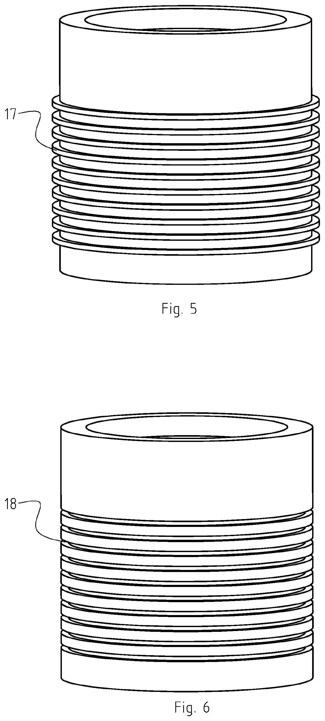
[0034]Referring to FIG. 5, an outer peripheral surface of a cylinder 4 is provided with a plurality of vertical ribs 17 in parallel along an axial direction of the cylinder 4, the vertical ribs 17 are perpendicular to the outer peripheral surface of the cylinder 4 and are arranged radially outward, a channel formed between adjacent vertical ribs 17 is used to receive air flow from air inlet holes 12, the channel is arranged in parallel with the air inlet holes 12, such arrangement achieves that air flow sweeps across surface of the vertical ribs 17 and takes away heat of the cylinder 4 while not generating resistance to rotation of the cylinder 4.


PUM


Abstract

A device has a shield boxes with a plurality of batteries installed, an inner wall of the shield box has a condenser pipe filled with coolant, a cylinder rotatably connects with an inner bottom of the shield box, an upper end of the cylinder has a circular groove arranged coaxially with the cylinder, the circular groove is sealed and rotated to connect with a circular block, a water inlet end and a water outlet end of the condenser pipe are both sealed and penetrated through the circular block, a heat insulation plate is arranged in the cylinder, the heat insulation plate divides the cylinder into two insulation chambers of the same size, an upper end of the cylinder is provided with two through holes communicating with the circular groove, a driving device for driving the cylinder to rotate is installed in the cylinder.

Description

CROSS-REFERENCE TO RELATED APPLICATIONS[0001]This application claims priority benefit of Chinese Patent Application No. 201910947783.7 filed on 8 Oct. 2019. The above-referenced application is hereby incorporated herein by reference.BACKGROUND OF THE INVENTION[0002]The invention relates to new energy vehicles, especially to battery cooling systems for new energy vehicles.[0003]New energy vehicles driven by electric energy are also called electric vehicles, and their power sources mainly include lithium-ion batteries, nickel-hydrogen batteries, fuel cells, and lead-acid batteries. During driving of electric vehicles, due to heating effect of current, batteries in vehicles will generate high temperature, and when temperature is too high, it will seriously affect performance and life of the battery. In existing technical means, in order to solve this problem, most of heat dissipation is performed by a cooling fan, for example, “New energy vehicle battery heat sink” is disclosed by appl...

Claims


Application Information

Patent Timeline
IPC IPC(8): H01M10/6556H01M10/613H01M10/625H01M10/658H01M10/6554H01M10/44
CPCH01M10/6556H01M10/613H01M10/44H01M10/658H01M10/6554H01M10/625H01M10/6551H01M10/6569H01M50/20H01M50/24H01M10/6552B60L3/0046B60L58/26Y02E60/10Y02T10/70
Inventor ZHU, GONG
Owner ZHU GONG
Why Eureka
Try Eureka