Fuel cell vehicle
- Summary
- Abstract
- Description
- Claims
- Application Information
AI Technical Summary
Benefits of technology
Problems solved by technology
Method used
Image
Examples
first modified embodiment
[0067]A buffer 70A shown in FIG. 6A includes a buffer tank 90. The buffer tank 90 has an extension length (axial length of the cylinder) which is longer than that of the buffer tank 80, so that the buffer tank 90 has a larger volume of internal space 90a which is larger than the buffer tank 80. A two dot chain line in the buffer tank 90 in FIG. 6A shows an increased area 91 by which the buffer tank 90 is larger in size than the buffer tank 80. That is, in the buffer 70, 70A, even in the case where there are constraints on the accommodation layout of the front box Fb in the radial direction, by changing the longitudinal length of the buffer tank 80, 90 (the length in one direction), it is possible to reset (change) the volume of the buffer tank 80, 90 easily.
second modified embodiment
[0068]A buffer 70B shown in FIG. 6B includes a buffer tank 92. The buffer tank 92 has a radial length which is longer than that of the buffer tank 80, so that the volume of internal space 92a of the buffer tank 92 is larger than that of the buffer tank 80. A two dot chain line in the buffer tank 92 in FIG. 6B shows an increased area 93 by which the buffer tank 92 is larger in size than the buffer tank 80. That is, in the buffer 70, 70B, even in the case where there are constraints on the accommodation layout of the front box Fb in the longitudinal direction of the buffer tank 80, 92, by changing the length in the radial direction, it is possible to reset (change) the volume of the buffer tank 80, 92 easily.
[0069]In this regard, in the vehicle 10, the suppression level of the pressure pulsation may be subject to the change or the shape change of the component parts of the fuel cell system 11. For dealing with such a situation, in the buffer 70, 70A, 70B, by changing the length of th...
fourth modified embodiment
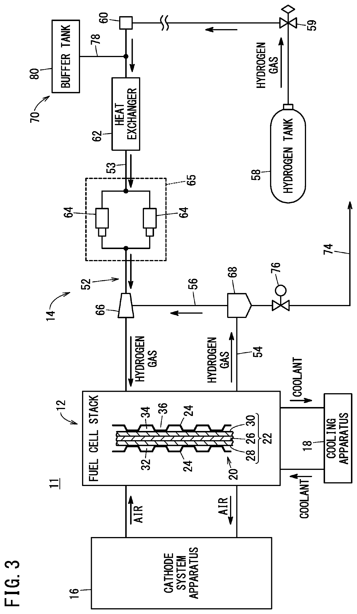
[0071]Further, a buffer 70D shown in FIG. 6D has a structural unit 98 for allowing an operator to adjust the diameters (inner diameters) at the positions adjacent to connection portion between the hydrogen gas supply pipe 52 and the branch pipe 78. Specifically, the structural unit 98 can adjust at least one of the diameter of the branch pipe 78 at a position “a” adjacent to a connection portion, the diameter of the hydrogen gas supply pipe 52 at a position “b” adjacent to the upstream side of a connection portion connected to the branch pipe 78, and the diameter of the hydrogen gas supply pipe 52 at a position “c” adjacent to the downstream side of the connection portion connected to the branch pipe 78. In the buffer 70D, since the diameter of each of the positions “a” to “c” is adjusted suitably, it is possible to effectively suppress pressure pulsation relative to the volume change in the hydrogen gas supply pipe 52 and / or the buffer tank 80.
[0072]Technical concepts and advantag...
PUM
 Abstract
Description
Claims
Application Information
 - R&D
- Intellectual Property
- Life Sciences
- Materials
- Tech Scout
- Unparalleled Data Quality
- Higher Quality Content
- 60% Fewer Hallucinations
Browse by: Latest US Patents, China's latest patents, Technical Efficacy Thesaurus, Application Domain, Technology Topic, Popular Technical Reports.
© 2025 PatSnap. All rights reserved.Legal|Privacy policy|Modern Slavery Act Transparency Statement|Sitemap|About US| Contact US: help@patsnap.com


