Device for installing a cylindrical gradient coil in a cylindrical magnet of a magnetic resonance system

a magnetic resonance system and gradient coil technology, which is applied in the field of devices for installing gradient coils in the cylindrical main field magnets of magnetic resonance systems, can solve the problems of complicated mounting devices as well as their operation, and achieve the effect of simplifying the operation and facilitating the installation

Inactive Publication Date: 2007-08-09
SIEMENS AG
View PDF13 Cites 1 Cited by
  • Summary
  • Abstract
  • Description
  • Claims
  • Application Information

AI Technical Summary

Benefits of technology

[0005] An object of the invention is to provide an improved device that is simplified in terms of its operation, and that facilitates the installation of the usually essentially cylindrical gradient coil into the usually hollow cylindrical main field magnet.
[0008] The inventive frame is significantly easier to handle than conventional frames after the frame is inserted completely into the magnet. Complicated installation steps as in the prior art for lengthening the bearer, etc, are not necessary. The frame is composed of a few parts, with all components used on the frame, such as the devices for generating the air cushion and the transportation facility such as the already described trolley for instance, being manufactured from non-magnetic materials, so that the gradient coil can be mounted with the magnetic field in place. It is thus not necessary to shut down the main field magnet in order to install or remove a gradient coil, which with large magnets in particular, such as a 7 T-magnets, requires several days.
[0009] In a further embodiment of the invention, a curved support element, adjusted in terms of its radius relative to the radius of the hollow cylindrical magnet is provided on each support. On the exterior of this support element, at least one seal acting on the base is provided, and on which at least one outlet opening for supplied air is provided in the region sealed by the seal. In accordance with the invention, the support element on the support side is adjusted in terms of its radius to that of the magnet bore, so that a relatively large surface area around the magnetic field bore can be sealed by the sealing means provided on the bearer side. Air is forced into this region by an external pressurized air supply, this air then discharging below the seal and forming the thin air film and / or air cushion. This means that the air cushion is generated on a relatively large surface, so that a more secure guidance of the frame is also provided in the magnet.
[0013] For simple accommodation of the gradient coil to be installed or de-installed, as well as for simple dismantling of the frame after positioning the gradient coil, the coil carrier can be formed of two detachably connected parts. Alternatively, at least one support is detachably connected to the coil carrier.
[0014] As already described, the invention expediently further has a transportation or positioning unit for the frame. A trolley is preferably used, so that the frame, together with gradient coil to be used, can be assembled away from the magnet and can only be transported to the magnet when required. A trolley having a base adjusted to the shape of the device on the support side for generating an air cushion is preferably used, with the base preferably likewise being curved and its radius corresponding to that of the cylindrical magnet. In other words, the base virtually continues the surface of the inner wall of the magnet bore, so that the frame can be inserted continuously into the magnet from the base of the trolley. The base itself, or as the case may be also the entire trolley, can be height adjustable, so that the base can be aligned exactly in relation to the magnetic field bore and can compensate for any possible step to the magnet.
[0016] The trolley itself is preferably mounted on rollers, and if applicable can also include a device for generating an air cushion to carry the trolley. The trolley can be positioned roughly with respect to the magnetic field bore by the rollers. An exact alignment then can be achieved after generating the air cushion which lifts the trolley by a minimal amount, as the trolley can be extremely easily moved on the air cushion and subsequently aligned, if applicable in conjunction with docking elements provided on the carriage and magnet sides.

Problems solved by technology

Fitting a gradient coil into the cylindrical main field magnet of a magnetic resonance system is a complicated, operation not least because of the considerable weight of the gradient coil as well as the available space.
This mounting device as well as its operation is complicated and requires a series of individual installation and dismantling steps.
With longer systems in particular, especially with systems having a 7 T-main field magnet, having a length of significantly more than 3 m, difficulties arise due to the large overall length of the carrier, which must accommodate the overall gradient coil load.

Method used


Image

  • Device for installing a cylindrical gradient coil in a cylindrical magnet of a magnetic resonance system
  • Device for installing a cylindrical gradient coil in a cylindrical magnet of a magnetic resonance system
  • Device for installing a cylindrical gradient coil in a cylindrical magnet of a magnetic resonance system

Examples


Embodiment Construction

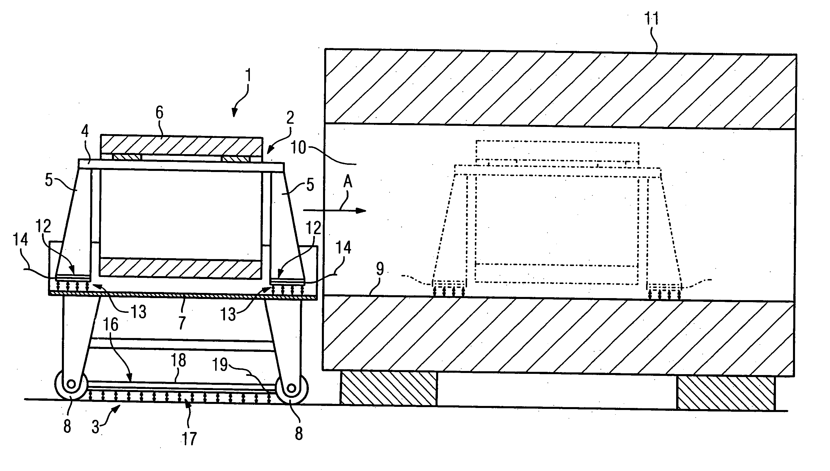
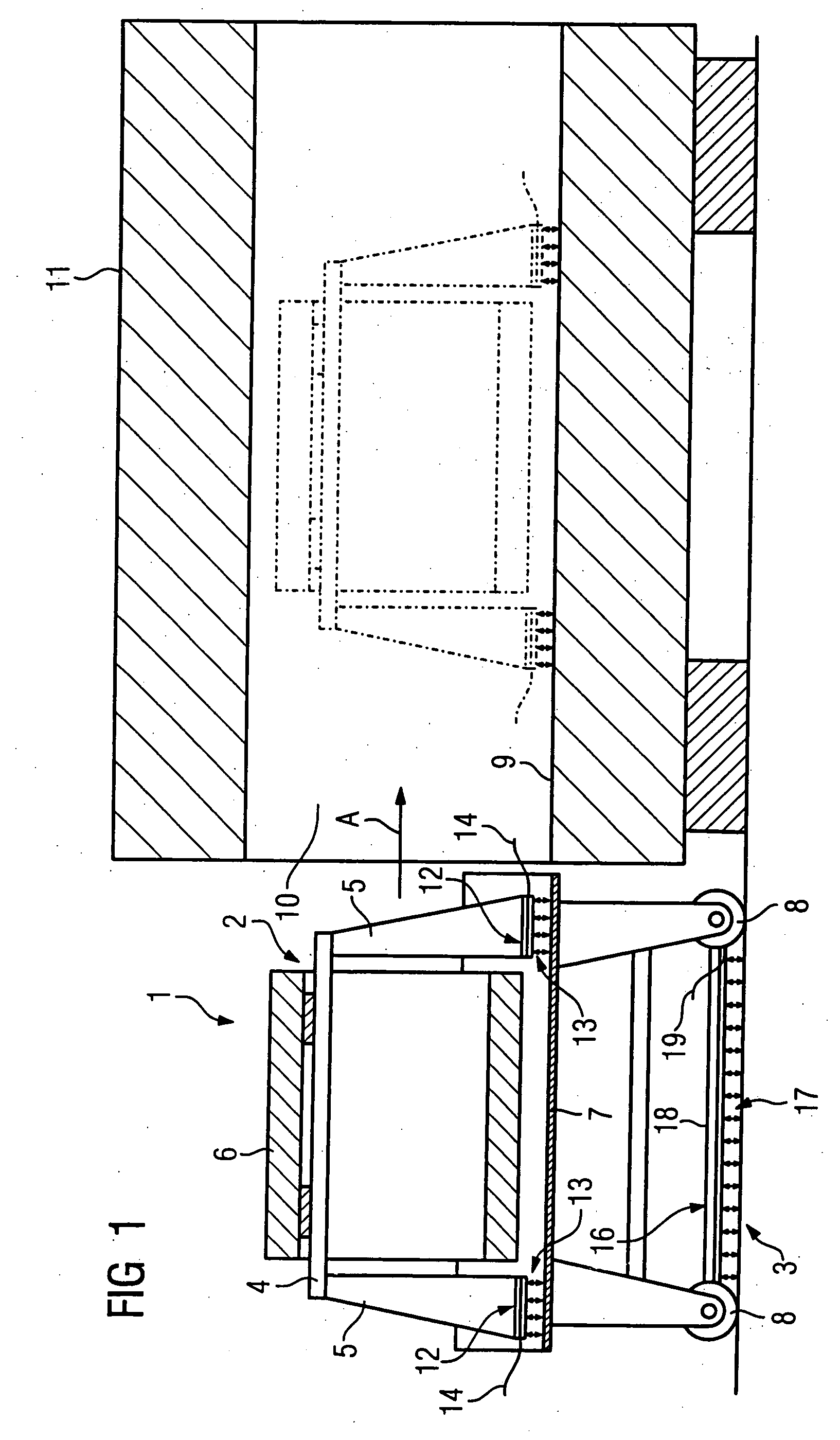
[0020]FIG. 1 shows an inventive device 1, having a frame 2 and a trolley 3.

[0021] The frame 2 has a coil carrier 4, on the ends of which are provided two supports 5, with which the frame 2 with the gradient coil 6 on the coil carrier 4 stands and / or is supported on a base, here the base 7 of the trolley 3. The frame 2 can be dismantled into at least two parts, in other words, the coil carrier 4 is in two-pieces and can be taken apart. Alternatively it is also conceivable to detach one of the supports 5 in a simple manner from the coil carrier 4, in order to insert the frame 2 either to accommodate a gradient coil 6 or to dismantle and remove the frame again after inserting a gradient coil 6.

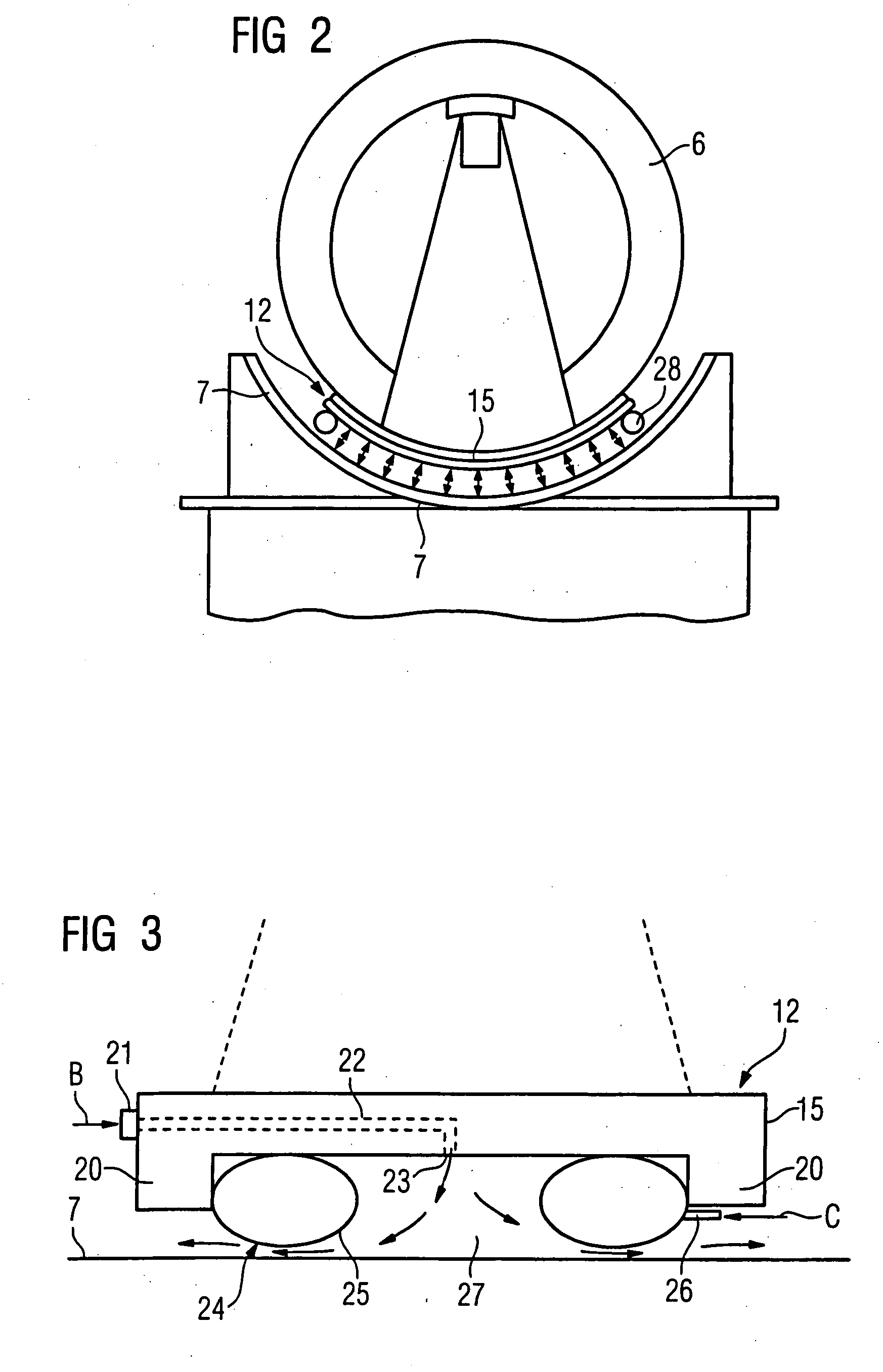
[0022] The trolley 3 is mounted in a moveable fashion on rollers 8. The base 7, see FIG. 2, is a curved design, with the curve radius corresponding as accurately as possible to the radius of the inner wall 9 of the bore 10 of the cylindrical main field magnet 11, which is part of a magnetic res...


PUM

PropertyMeasurementUnit
lengthaaaaaaaaaa
lengthaaaaaaaaaa
bore radiusaaaaaaaaaa

Abstract

A device for installing a gradient coil into a magnet of a magnetic resonance system has a frame with a coil carrier passing through the gradient coil and accommodating the gradient coil. The coil carrier is arranged on two lateral supports, upon which the frame stands on the base, with devices for generating an air cushion that carries the frame being provided on the supports.

Description

BACKGROUND OF THE INVENTION [0001] 1. Field of the Invention [0002] The invention relates to a device for installing a usually cylindrical gradient coil in a usually hollow cylindrical magnet of a magnetic resonance system, of the type having a frame with a coil carrier passing through the gradient coil and accommodating it, the coil carrier being arranged on two lateral supports, on which the frame stands on the base. [0003] 2. Description of the Prior Art [0004] Fitting a gradient coil into the cylindrical main field magnet of a magnetic resonance system is a complicated, operation not least because of the considerable weight of the gradient coil as well as the available space. An installation device thus is used to fit the coil. This has a frame with a coil carrier, which rests on the floor on two lateral supports. The coil carrier passes through the coil that is suspended thereon. For installation, this frame is moved as near as possible to the main field magnet. In order to be ...

Claims


Application Information

Patent Timeline
Patent Type & Authority Applications(United States)
IPC IPC(8): B23P19/00
CPCG01R33/385Y10T29/53265G01R33/3858
Inventor DIETZ, PETERSCHUSTER, JOHANNSTOCKER, STEFAN
Owner SIEMENS AG
Why Eureka
Try Eureka