Filter Element Having Optimized Flow Control
a filter element and flow control technology, applied in the direction of dispersed particle separation, chemistry apparatus and processes, separation processes, etc., can solve the problems of disadvantageous use of filter elements with a decreased flow control and filtering action, and disadvantageous complex manufacture of fold sheets of different lengths
- Summary
- Abstract
- Description
- Claims
- Application Information
AI Technical Summary
Benefits of technology
Problems solved by technology
Method used
Image

Examples
second embodiment
[0052]the air filter 110 according to the invention is isometrically illustrated in FIG. 7. The air filter 110 comprises a second guiding rib 710 at the housing cover 114. This second guiding rib 710 is embodied in the form of an indentation of the housing cover 114. It extends at least in sections thereof above and parallel to a first guiding rib 212 (see FIG. 10). Moreover, it can be arranged with one end at the outlet 120.
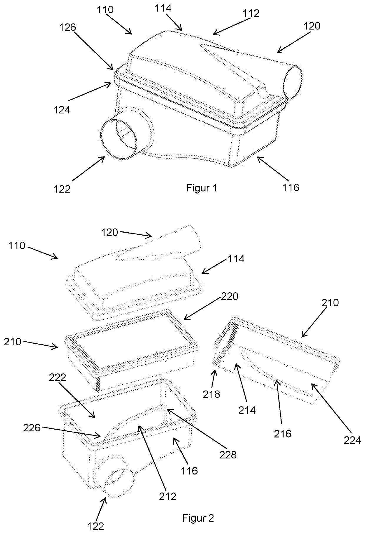
[0053]FIG. 8 shows separately, respectively, the housing bottom 116 and the housing cover 114 of the air filter 110 and the filter element 210 of the second embodiment. The filter element 210 comprises a filter medium 214. The filter medium 214 comprises an upwardly oriented second recess 810. The second guiding rib 710 can be inserted, in particular at least partially, into this second recess 810 with form fit when the filter element 210 is placed on the housing bottom 116.
[0054]FIG. 9 shows a plan view of the second embodiment of the air filter 110.
[0055]FIG. ...
third embodiment
[0056]FIG. 11 shows separately, respectively, the housing bottom 116 and the housing cover 114 of the air filter 110 and the filter element 210 in a The air filter 110 comprises again a second guiding rib 710 at the housing cover 114. This second guiding rib 710 is embodied in the form of an indentation at the housing cover 114. It extends above and at least in sections thereof parallel to the first guiding rib 212. Moreover, it is preferably arranged with one end at the outlet 120. The filter element 210 comprises a first filter medium body 1110 and a second filter medium body 1112. The guiding rib 212 comprises a cutout 1116 in a section at its end arranged at the inlet 122. A sealing strip 1114 is seal-tightly arranged between the first filter medium body 1110 and the second filter medium body 1112. The sealing strip 1114 extend at least in sections thereof parallel to the guiding rib 212 and to the second guiding rib 710.
[0057]FIG. 12 shows a plan view of the third embodiment o...
fourth embodiment
[0060]FIG. 15 shows separately, respectively, the housing bottom 116 and the housing cover 114 of the air filter 110 and the filter element 210 in a The filter element 210 comprises again a first filter medium body 1110 and a second filter medium body 1112. A sealing strip 1114 is air-tightly arranged between the first filter medium body 1110 and the second filter medium body 1112. The sealing strip 1114 extends above and in sections thereof parallel to the guiding rib 212.
[0061]FIG. 16 shows a plan view of the fourth embodiment of the air filter 110.
[0062]FIG. 17 shows a cross section of the fourth embodiment of the air filter 110 along the line DD=in FIG. 16. In a separation region 1710, a slot-shaped cavity 1712 is formed between the sealing strip 1114 and the first guiding rib 212. The first filter medium body 1110 and the second filter medium body 1112 are arranged along one side of the guiding rib 212, of the opening 1712, and of the sealing strip 1114, respectively. Both sid...
PUM
| Property | Measurement | Unit |
|---|---|---|
| Length | aaaaa | aaaaa |
| Flow rate | aaaaa | aaaaa |
| Shape | aaaaa | aaaaa |
Abstract
Description
Claims
Application Information
 - R&D
- Intellectual Property
- Life Sciences
- Materials
- Tech Scout
- Unparalleled Data Quality
- Higher Quality Content
- 60% Fewer Hallucinations
Browse by: Latest US Patents, China's latest patents, Technical Efficacy Thesaurus, Application Domain, Technology Topic, Popular Technical Reports.
© 2025 PatSnap. All rights reserved.Legal|Privacy policy|Modern Slavery Act Transparency Statement|Sitemap|About US| Contact US: help@patsnap.com