
Linear lighting system

a lighting system and linear technology, applied in the direction of fixed installation, lighting and heating equipment, lighting support devices, etc., can solve the problems of frequent (at least annually) lamp failure, uneven lighting of the traffic surface and tunnel walls,

Inactive Publication Date: 2009-08-20
LSI INDS
View PDF15 Cites 161 Cited by
  • Summary
  • Abstract
  • Description
  • Claims
  • Application Information

AI Technical Summary

Benefits of technology

[0015]The housing also typically has a gasket means to create a moisture seal between the longitudinal side of the light-transmitting window and the pocket or receiving portion of the arm of the housing. The housing also typically has a means for enclosing, preferably sealing off, the opposed longitudinal ends of the elongated housing. The LEDs can have an associated light-controlling reflector having a proximal opening disposed around the base of the LED, and a distal opening defined by a distal rim disposed adjacent to the inner surface of the elongated window to create a light barrier that prevents LED light from escaping between the rim and the inner surface of the window.

Problems solved by technology

Tunnel and bridge lighting have used incandescent, fluorescent and more recently high intensity discharge (HID) lamps that can provide adequate amounts of lighting, but which have several drawbacks, including frequent (at least annually) lamp failures and uneven lighting of the traffic surface and tunnel walls.
The variability in the types of tunnels and driving conditions makes it a challenge to develop a lighting system that can be installed and easily adapted to any tunnel.

Method used


Image

  • Linear lighting system
  • Linear lighting system
  • Linear lighting system

Examples


Embodiment Construction

Linear Luminaire

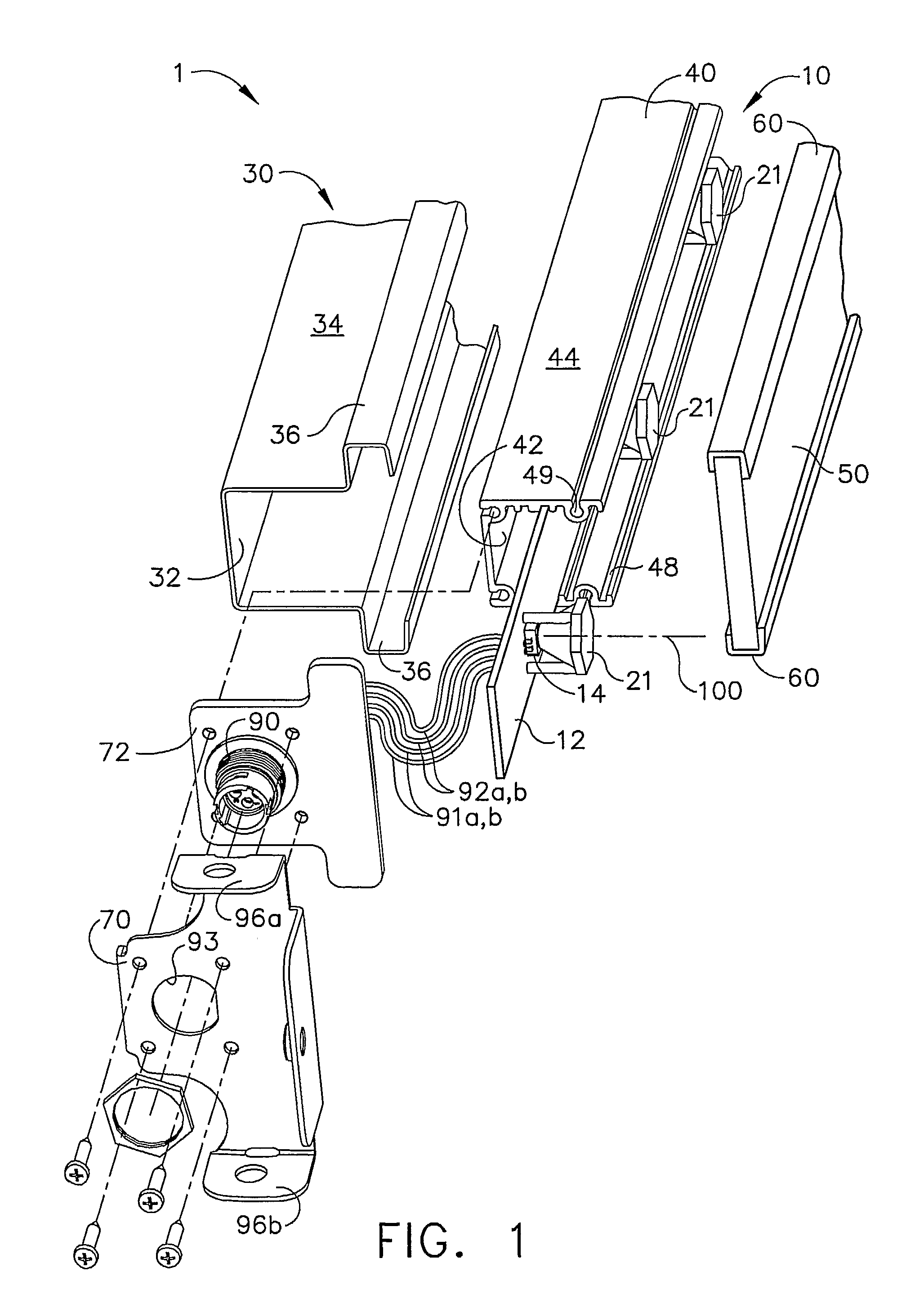
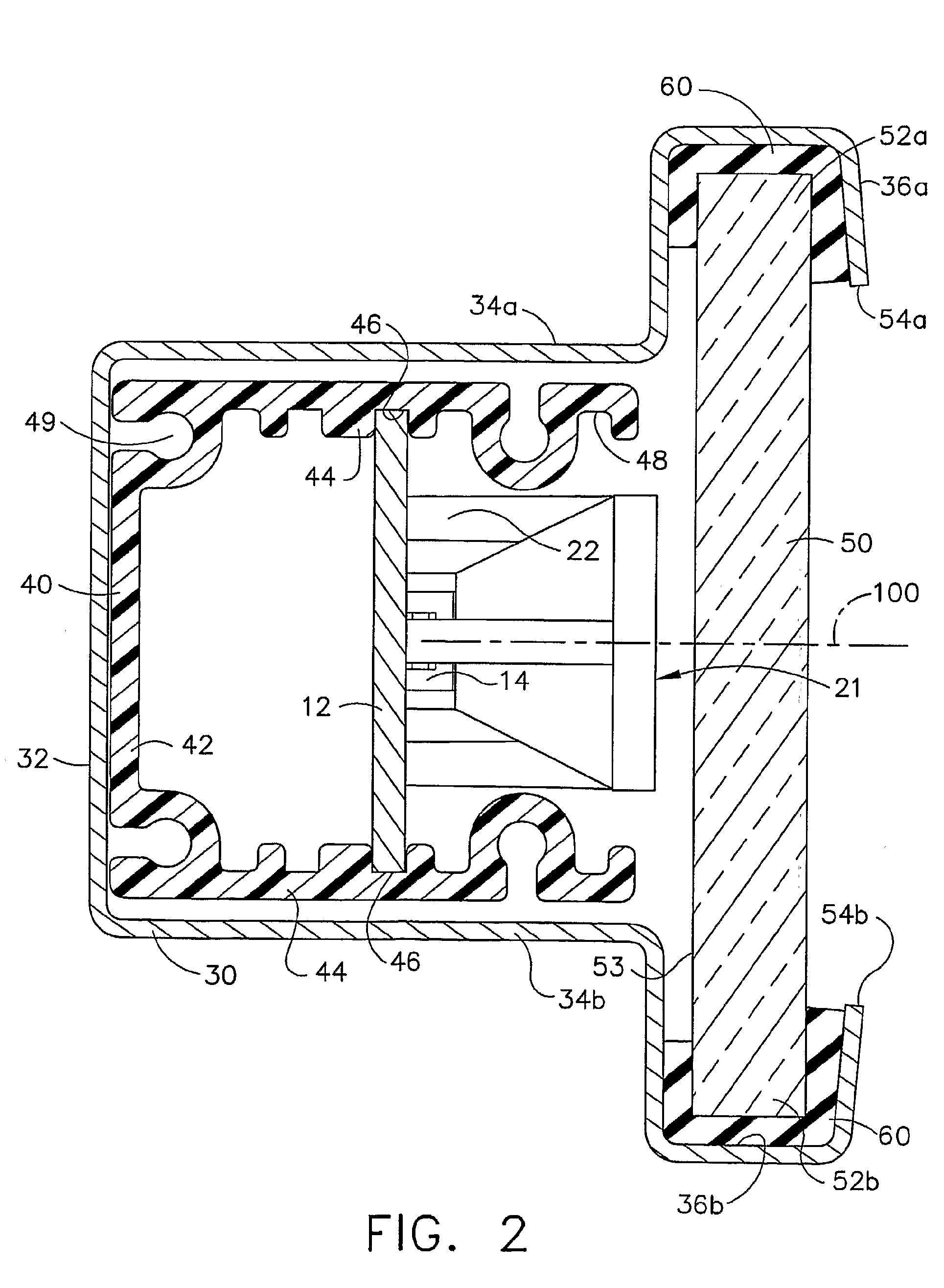
[0038]FIG. 1 shows an exploded view of a linear luminaire 1 consisting of a linear array light fixture 10, a housing 30, and a light-transmitting window 50. FIG. 2 shows a sectional view of the linear luminaire.

[0039]The illuminating heart of the linear luminaire 1 is the linear array light fixture 10 having an elongated light board 12 and the plurality of discrete light emitting diodes (LEDs) 14. The LEDs are arranged in a substantially linear array along the length of the elongated light board 12. The array is shown as a single line of LEDs, centered at a longitudinal distance of at least 0.5 cm, and up to about 50 cm, though more typically at least 2 cm, and up to about 20 cm.

[0040]The linear array of LEDs can include a series of LEDs wherein some of the LEDs are staggered, for example where alternating LEDs are raised slightly above or dropped below a main line of LEDs.

[0041]The elongated light board 12 is typically a metallic clad resin board, typically aluminum...


PUM


Abstract

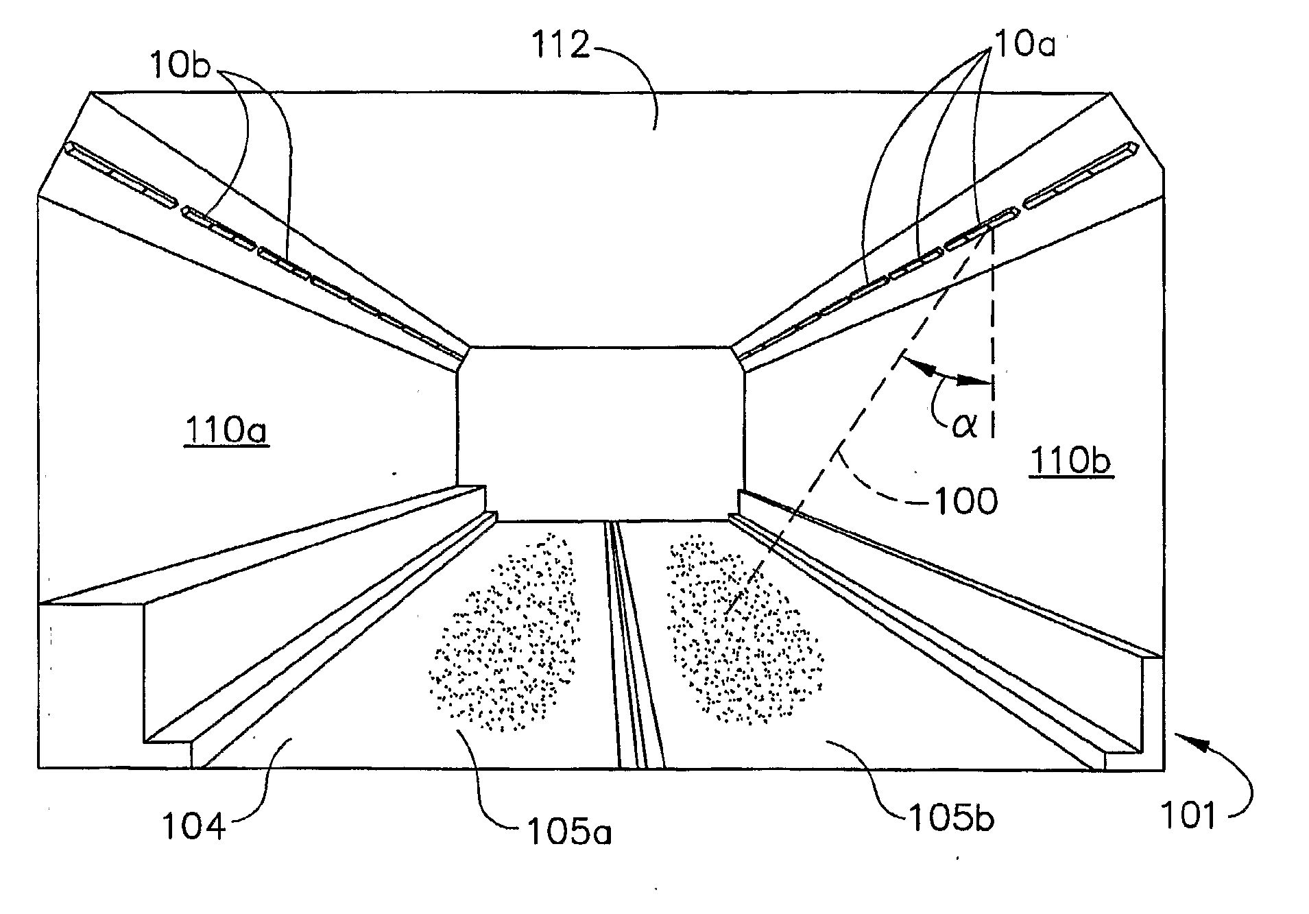
A linear light system, and a linear luminaire used in the system, for lighting a traffic surface. The linear luminaire has a plurality of light emitting diodes (LEDs) disposed in a linear matrix along the length of the traffic surface, and a plurality of refractive lenses for directing the emitted light from the LEDs at the traffic surface. The traffic surface is typically the roadway of a tunnel. A refractor lens is used to direct the emitted light from the LEDs predominantly toward at least the traffic surface.

Description

BACKGROUND OF THE INVENTION[0001]Light emitting diodes (LEDs) have improved in terms of quality, performance and cost, and their use and popularity have been growing. LED lighting provides, and has the further potential, to reduce the power consumption per unit lumen.[0002]Tunnel and bridge lighting have used incandescent, fluorescent and more recently high intensity discharge (HID) lamps that can provide adequate amounts of lighting, but which have several drawbacks, including frequent (at least annually) lamp failures and uneven lighting of the traffic surface and tunnel walls. Tunnels for highways and roadway can have earthen or rock walls and ceilings, or constructed walls or ceilings made or lined with concrete, ceramic tile, or other construction material. Tunnels also come in a wide variety of shapes and sizes. Some tunnels have a domed ceiling and wall shape, while others have vertical walls and substantially horizontal ceilings. Some tunnels are short, allowing one to easil...

Claims


Application Information

Patent Timeline
Patent Type & Authority Applications(United States)
IPC IPC(8): F21S4/00F21V21/00F21V1/00
CPCF21S2/005F21S4/008F21S8/033F21W2131/101F21Y2101/02F21V5/04F21S4/28F21Y2115/10
Inventor REED, MARK C.BOYER, JOHN DELMORE
Owner LSI INDS
Learn More