
Implantable ventricular assist device

a technology of ventricular assist and ventricular valve, which is applied in the field of ventricular assist devices, can solve the problems of many unsolved problems, cardiac rupture, hemorrhage and infection, and cannot effectively integrate the anatomical and physiological properties of the heart, so as to achieve effective blood flow inside the body, maintain effective diastolic expansion of the ventricle, and effectively balance the change of the ventricle

Active Publication Date: 2021-03-25
LIU MARVIN
View PDF0 Cites 1 Cited by
  • Summary
  • Abstract
  • Description
  • Claims
  • Application Information

AI Technical Summary

Benefits of technology

The patent describes a ventricular assist device that uses a double chamber extrusion driving system and a balloon-like structure to effectively pump and suck blood in the heart without needing a mechanical motor drive. This device contains a permanent magnetic field and a soft, elastic material for the balloon-like structure to ensure effective diastolic expansion of the ventricle and prevent thrombosis. The device can be controlled from outside the body and is noninvasive, reducing energy consumption and improving driving efficiency.

Problems solved by technology

However, all of them are the mechanical blood pumping device only and do not effectively integrate the anatomical and physiological properties of the heart.
Magnetically levitated centrifugal pump as the most sufficient ventricular assist device so far, has many unsolved problem in clinical use, such as cardiac rupture, hemorrhage and infection, lifetime anticoagulation, non-pulsatile perfusion and high cost.

Method used


Image

  • Implantable ventricular assist device
  • Implantable ventricular assist device
  • Implantable ventricular assist device

Examples


example 1

Observation on the Ventricular Assisting Effect of a Closed Intraventricular Stent (Referring to FIG. 27, 29)

[0090]The experimental materials included a heart model, a stainless steel wire, a stainless steel rod, a latex balloon, a silicon tube, a waterproof polyester fiber chamber, a permanent magnet pad, a servo motor, a battery and a spring.

[0091]The experimental device was prepared as follows. The heart model 79 with a ventricle volume of about 100 mL was established by 3D printing, which includes the front half and the rear half printed separately and then sealed together for a whole heart. Each valve of the heart model was replaced with a check valve, which was, the check valve was fixedly bound to the site where the heart valve should be. A cage-like intraventricular stent 69 was prepared from the stainless steel wire. A latex balloon 68 with a volume of about 100 mL was prepared with 1 mm-thick latex. The driving chamber 64 having a volume of about 120 mL was prepared from t...

example 2

Observation on the Ventricular Assisting Effect of an Open Intraventricular Stent (Referring to FIGS. 28, 29)

[0093]The experimental materials were referred to Example 1.

[0094]The preparation of the experimental device in this example was basically identical with Example 1 except for the use of a round-tubular upper-lower opened intraventricular stent.

[0095]The experimental method and results were described as follows. Connected the liquid inlet with the pulmonary vein 6, and further connected to a deionized water output, so that the deionized water filled into the atrium 8 and the ventricle 5. The second permanent magnet pad 66 was manually moved to the right side, it attracted the first permanent magnet pad 63 and we saw the first permanent magnet pad 63 simultaneously moves along the sliding rail 75 toward the second permanent magnet pad 66 to pressurize the driving chamber 64, the water in the driving chamber 64 was driven to flow into the latex balloon 68 through the driving tub...

example 3

Observation on the Ventricular Assisting Effect by Electromagnetic Driving System (Referring to FIG. 29)

[0096]The experimental materials included a PWM modulator, and an iron pad instead of the first permanent magnet pad and an electromagnetic pad instead of the second permanent magnet pad. The servo motor was not required here and other materials were referred to Example 1.

[0097]The experimental device was prepared as follows. The heart model 79 with a ventricle volume of about 100 mL was established by 3D printing, which includes the front half and the rear half printed separately and then sealed together for a whole heart. Each valve of the heart model was replaced with a check valve, which was, the check valve was fixedly bound to the site where the heart valve should be. A cage-like intraventricular stent 69 was prepared from the stainless steel wire. A latex balloon 68 with a volume of about 100 mL was prepared with 1 mm-thick latex. The driving chamber 73 having a volume of a...


PUM


Abstract

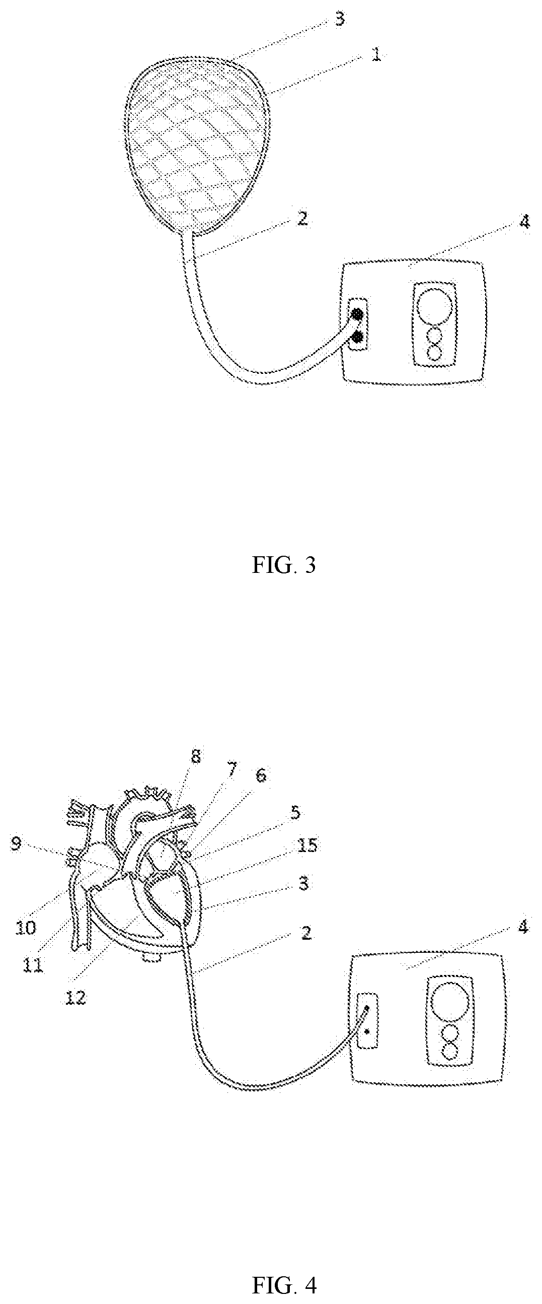
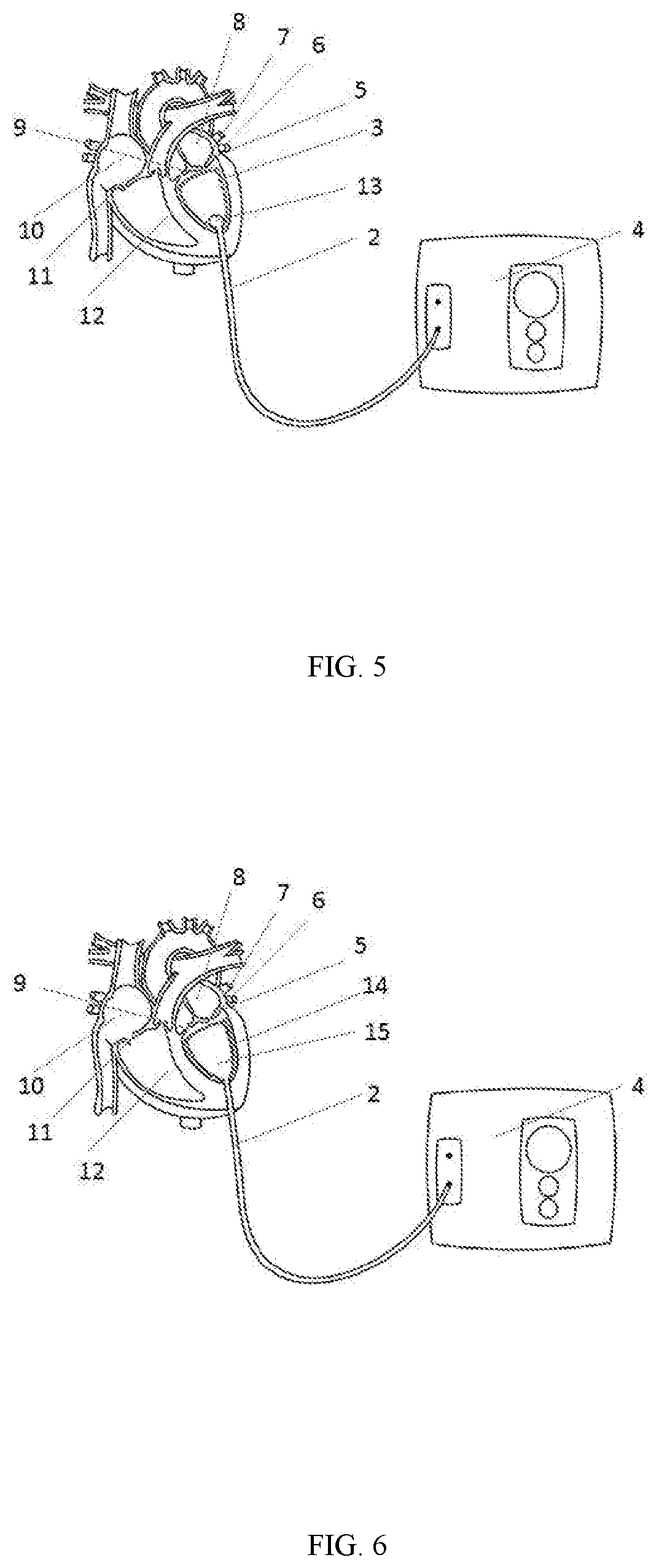
An implantable ventricular assist device comprises an intraventricular stent used for the creation of an artificial chamber inside the ventricle, a balloon-like structure used to drive the change of the artificial chamber between a contractile configuration and a diastolic configuration, a power system used for driving the change of the balloon-like structure between the contractile configuration and the diastolic configuration. There is also a power system and a mechanical design to operate the system working, wherein in the contractile configuration, the balloon-like structure expands and occupies the space of the artificial chamber and drives the blood inside the artificial chamber flow outside the artificial chamber, wherein in the diastolic configuration, the balloon-like structure shrinks and releases the space inside the artificial chamber, and the blood outside the artificial chamber flows back into the artificial chamber. It is easy to reach the goal of cardiac function.

Description

FIELD OF THE INVENTION[0001]The present invention relates to ventricular assist device and in particular to implantable ventricular assist device.DESCRIPTION OF THE RELATED ART[0002]Cardiovascular disease is the leading cause of death in the world, which includes coronary artery diseases such as angina and myocardial infarction, the others such as heart failure, hypertensive heart disease, rheumatic heart disease, cardiomyopathy and heart arrhythmia. Heart failure is when the heart is unable to pump sufficiently to maintain blood flow to meet the body's needs, and has been one of the most common causes of death in cardiovascular disease, also known as congestive heart failure (CHF). It affected about 40 million people globally. Overall around 2% of adults have heart failure and in those over the age of 65, this increase to 6-10%. The risk of death is about 35% the first year after diagnosis and about 10% the year following, and similar to some cancers. Treatment depends on the sever...

Claims


Application Information

Patent Timeline
IPC IPC(8): A61M1/12A61M1/10A61F2/90
CPCA61M1/122A61M1/1044A61M1/1008A61M1/106A61M1/107A61F2/90A61F2250/0067A61M2230/04A61M2205/3317A61M2210/125A61F2210/0014A61M2205/0266A61M2205/0216A61M2205/07A61M60/17A61M60/295A61M60/497A61M60/861A61M60/515A61M60/148A61M60/274A61M60/857A61M60/869A61M60/187
Inventor LIU, MARVIN
Owner LIU MARVIN
Learn More