
Sliding member and bearing

a technology of sliding member and bearing, which is applied in the direction of sliding contact bearing, shock absorber, mechanical apparatus, etc., can solve the problems of limited use of pb in various fields, and achieve the effects of improving ride quality, increasing static friction force, and preventing abrasion

Active Publication Date: 2021-03-11
SENJU METAL IND CO LTD
View PDF0 Cites 0 Cited by
  • Summary
  • Abstract
  • Description
  • Claims
  • Application Information

AI Technical Summary

Benefits of technology

The present invention relates to a new type of sliding member that can be used in a shock absorber. By adding a specific amount of carbon fibers, the sliding member can increase its static friction force and reduce the rate of change in its dynamic friction force. This results in improved ride quality and prevents abrasion.

Problems solved by technology

On the other hand, use of Pb has been limited in various kinds of fields in recent years because of harmful effects to human health and a material without using Pb has been proposed for a sliding member.

Method used


Image

  • Sliding member and bearing
  • Sliding member and bearing
  • Sliding member and bearing

Examples


examples

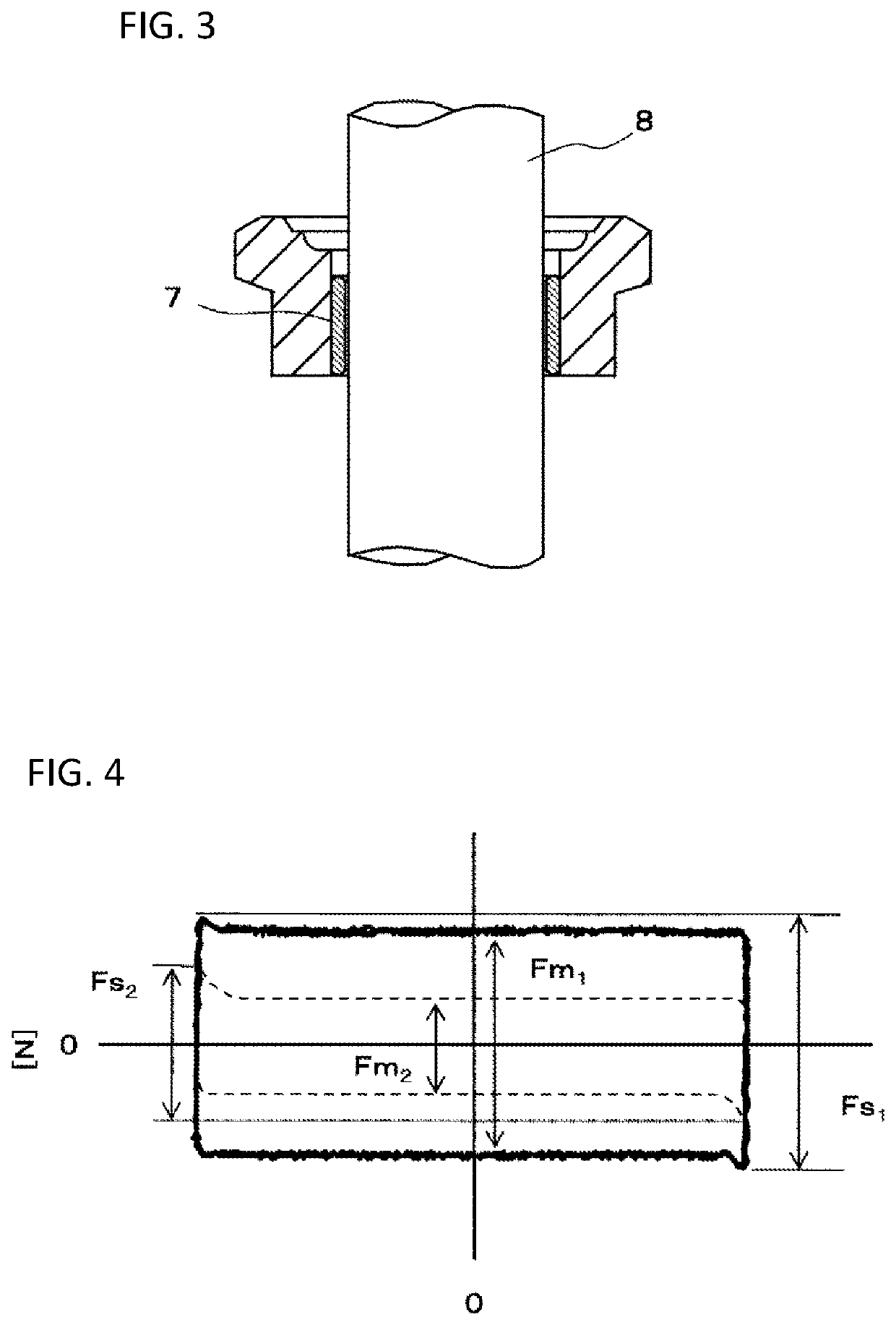
[0074]The guide bushings were prepared using the sliding members having compositions in Examples 1 to 7 and Comparison Examples 1 to 3, as shown in Table 1, and their static friction forces and their rates of change in the dynamic friction force in relation to the static friction force were measured.

(1) Verification Method

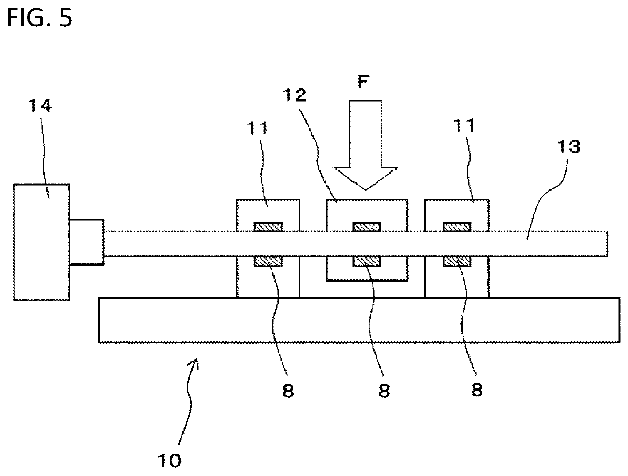
[0075]FIG. 5 shows a configuration example of a testing machine for measuring the static friction force and the dynamic friction force. In a testing machine 10, guide bushings 8 to be tested were mounted on bearing bases 11 and a load portion 12. Any traverse loads were applied to the load portion 12, via the guide bushing 8, between the bearing bases 11 supporting a rod 13 through the guide bushings 8. A friction force when vibrating the rod 13, to which the traverse load had been applied, by a vibrator (not shown), was measured by a load cell 14.

[0076]In Examples 1 to 7, a pitch-based carbon fiber having a fiber diameter of 13 μm, an average fiber length of 40 μm...


PUM

PropertyMeasurementUnit
weight %aaaaaaaaaa
weight %aaaaaaaaaa
weight %aaaaaaaaaa

Abstract

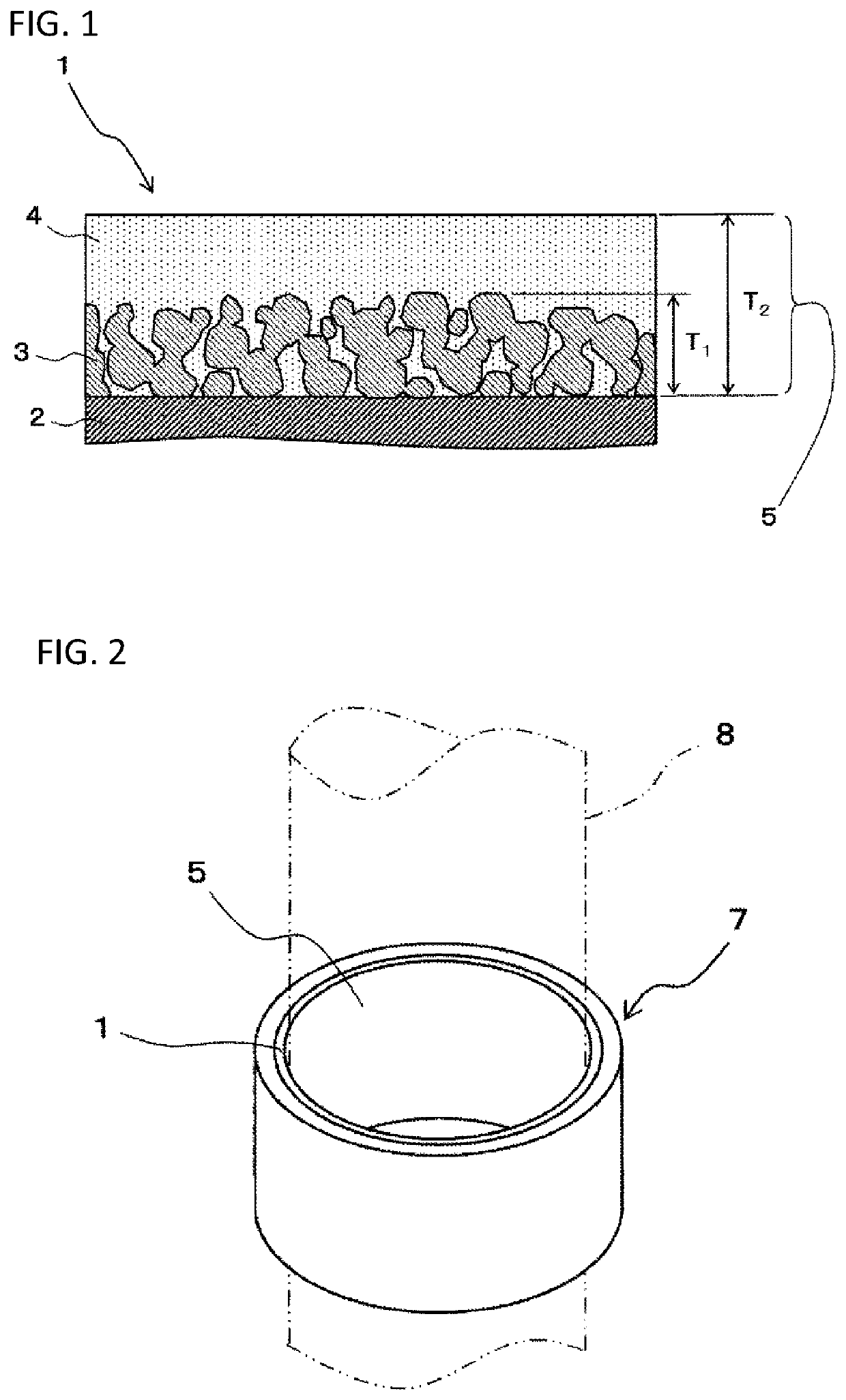
A sliding member includes a metallic substrate, a porous layer formed on a surface of the metallic substrate and a sliding layer that covers the porous layer. The porous layer is made of a metal itself or an alloy composition. The sliding layer is made of a lead-free resin composition. The resin composition consists of a pitch-based carbon fiber and a fluororesin, and assuming weight of the resin composition as 100, more than 10 weight % and 35 weight % or less of the pitch-based carbon fiber is contained.

Description

TECHNICAL FIELD[0001]The present invention relates to a sliding member slidably supporting a mated member and a bearing using the sliding member.BACKGROUND ART[0002]A sliding material having a so-called bimetal structure, namely, a two-layer structure in which a Cu-based alloy powder is sintered on a steel plate as a back plate has been often used as a sliding member. In this case, a surface of a metal layer on which the Cu-based alloy powder has been sintered becomes a sliding surface, so that good slidability is ensured by adding lead (Pb) to the Cu-based alloy powder which has been used in the past.[0003]On the other hand, use of Pb has been limited in various kinds of fields in recent years because of harmful effects to human health and a material without using Pb has been proposed for a sliding member. For example, a sliding member using a resin material is proposed as a sliding material without using Pb (see Patent Literature 1).[0004]Further, a past sliding member using the r...

Claims


Application Information

Patent Timeline
Patent Type & Authority Applications(United States)
IPC IPC(8): F16C33/12F16C17/02
CPCF16C33/128F16C33/121F16C2208/32F16C2204/50F16C2208/02F16C17/02C08K3/00C08K7/02C08L27/12F16C33/12F16C33/14F16C33/20F16F9/32C08F214/26C08K3/04C08K7/06C08K2003/0893C08K2003/2265C08K2003/3009F16C33/201F16C33/206F16C33/208F16C2208/30F16C2208/34F16C2326/05F16C2361/53F16F9/366F16F2222/04F16F2224/0241C08L27/18
Inventor KUROSAKI, KIMIHIKOTADOKORO, KENZOTOYODA, MINORU
Owner SENJU METAL IND CO LTD
Learn More