
Materials with high dielectric constant for magnetic resonance imaging instruments

a magnetic resonance imaging and dielectric constant technology, applied in the direction of instruments, magnetic measurement, magnetic variable regulation, etc., can solve the problems of not clearly defining the permittivity, no longer homogeneous water-charge composition, and blank signal areas

Pending Publication Date: 2021-03-04
CENT NAT DE LA RECHERCHE SCI +3
View PDF0 Cites 0 Cited by
  • Summary
  • Abstract
  • Description
  • Claims
  • Application Information

AI Technical Summary

Benefits of technology

The invention relates to a material used in high field and very high field magnetic resonance imaging instruments. The material comprises a polar solvent, a dispersant, and a dielectric charged component. The polar solvent has a melting point of 14°C to 50°C. The dispersant can be gums such as xanthan gum or phytagel. The dielectric charge component can be particles of SiC, BaTiO3, or CaTiO3, with average sizes ranging from 0.1 μm to 50 μm. The proportion of polar solvent is between 1% and 95% in volume, the proportion of dispersant is up to 40% in volume, and the proportion of dielectric material is between 5% and 99%. The material can be obtained by mixing the solvent and dispersant, adding the dielectric charge component, and stirring the mixture for a period of time. The technical effect of the invention is to provide a material that can improve the performance of magnetic resonance imaging instruments by improving the magnetic field homogeneity and reducing the eddy current noise.

Problems solved by technology

Depending on the organs and the field of the magnetic resonance imaging used, the regions to be observed have dimensions substantially similar to those of the radiofrequency wavelength, thus standing waves appear and result in signal blank areas.
However, it does not clearly define the permittivity that such pads should have neither the number of pads the helmet is made of.
However, the ideal permittivity range of pad use being between 150 and 300, these dielectric charges are loaded in quantities typically of about 40% in volume or more such that the water-charge composition is no longer homogeneous, because of porosity and agglomerates.
However, the dielectric charges demix from, the solvent after a few weeks due to their high concentration.
As a consequence, a significant risk of sedimentation exists that can completely transform the behavior of the pad until it renders it ineffective or risky for the patient because of the uncontrolled redistribution of the field, resulting in specific SAR problems.
In order to reduce it, additives such as Agar or Xanthan gums can be added in the composition but significantly deteriorate the mechanical properties of the pads.
Thus, these pads generally have a short life span due to water evaporation and particles sedimentation.
In addition, the manipulations that result from their regular use increase the risk of sedimentation of the material and therefore heterogeneities that imaged the performance of the pad.
In summary, the use of pads currently proposed in the literature is limited by its instability and short lifespan.

Method used


Image

  • Materials with high dielectric constant for magnetic resonance imaging instruments
  • Materials with high dielectric constant for magnetic resonance imaging instruments

Examples


example 1

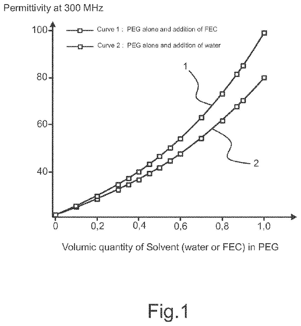
Simulation of Permittivity at 300 MHz Related to the Volume Solvent Amount in Polyethylene Glycol (PEG)

[0057]Polyethylene glycol (PEG) has been mixed with fluoroethylene carbonate (FEC) to demonstrate the permittivity evolution of this mixture compared to the permittivity evolution of the mixture containing polyethylene glycol and water (see FIG. 1).

[0058]As it is shown in FIG. 1, the permittivity of the mixtures increases with the volumetric amount of solvent. Moreover, the mixture with FEC displays better permittivity than the mixture containing water thus allowing to add more dispersant at a given permittivity level.

example 2

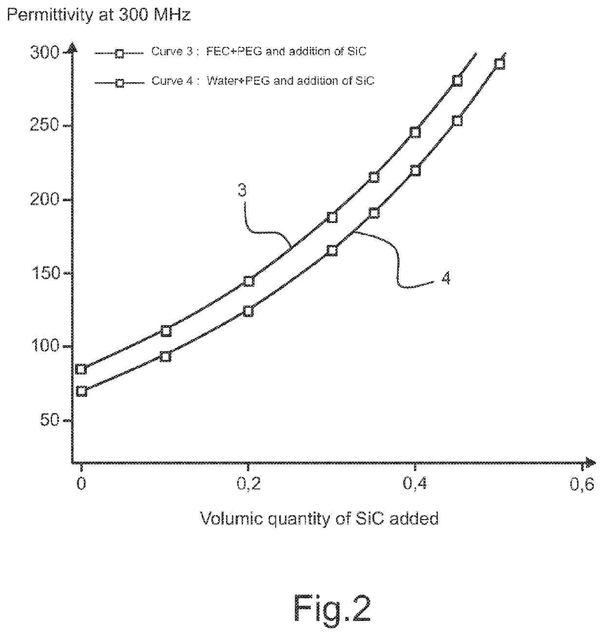
Simulation of Permittivity at 300 MHz Related to the Volumetric Amount of Filler

[0059]As it is shown. in FIG. 2, a mixture of EEC, PEG and SiC demonstrated better permittivity at 300 MHz, compared to the mixture of water, PEG and SiC.

[0060]This association of solvent having a melting point between 14° C. and 50° C., a dispersant and a dielectric charge aims in particular to prevent the sedimentation of particles, to easily control the viscosity of the matrix, to limit the risks of heterogeneity, and to limit the evaporation of the solvent, in order to obtain a pad as efficient as those based on barium titanate but more comfortable, with a longer lifespan and lower toxicity.

example 3

Required Quantities to Prepare 100 g of the Composite Material

[0061]The table 3 below features the quantities in g of the solvent (fluoroethylene carbonate—FEC) and dispersant (Polyethylene glycol—PEG) to be mixed for producing 100 g of solvent with dispersant:

TABLE 3% in volumeWeights (g)FEC10 to 99.513 to 99.6PEG0.5 to 90 0.4 to 87 

[0062]The table 4 below features the quantities in g of silicon carbide powder to be mixed with the solvent with dispersant for the production of 100g of composite:

TABLE 4% in volumeWeights (g)Solvent with10 to 95.5 4.5 to 87.7dispersantSiC4.5 to 90 12.3 to 95.5

[0063]The table 5 below features the quantities in g of silicon carbide powder, fludroethylene carbonate and Polyethylene glycol to mix for the realization of 169 g of composite in the ideal case:

TABLE 5% in volumeWeights (g)Solvent with5051.4dispersant (90vol. % EEC + 10vol. % PEG)SiC50117.6

[0064]The use of this matrix FEC+PEG with respect to the water makes it possible to have a real permittivi...


PUM


Abstract

The invention relates to a material for use as a pad in high field and / or very high field magnetic resonance imaging instrument, comprising at least one polar solvent having a melting point of 14° C. to 50° C., a dispersant and a dielectric charge. The invention relates also to a pad used in field of high field and / or very high field magnetic resonance imaging made of at least such a material.

Description

TECHNICAL FIELD OF THE INVENTION[0001]The invention relates to materials to locally adjust the radiofrequency field generation in magnetic resonance imaging (MRI) instruments, pads comprising said materials, and methods for obtaining such materials.BACKGROUND OF THE INVENTION[0002]Magnetic resonance imaging is a method of obtaining images of the interiors of objects, especially living things such as humans and animals. It does not use ionizing radiation such as X-rays. Instead, it employs radio-frequency waves and intense magnetic fields to excite atoms in the object under evaluation. Patterns in this excitation are observed on a display. Magnetic resonance imaging can provide real-time, three-dial views of body organs, muscles, and joints without invasive surgery.[0003]Magnetic resonance imaging with high field, such as a three Tesla field, and very high field of seven Tesla or more, theoretically allows to obtain images with spatial and / or temporal resolutions that are improved co...

Claims


Application Information

Patent Timeline
IPC IPC(8): G01R33/28G01R33/565
CPCG01R33/288G01R33/5659
Inventor REDHA, ABDEDDAIMADENOT-ENGELVIN, ANNE-LISEDUBOIS, MARCENOCH, STEFANMALLEJAC, NICOLASRAOLISON, ZOSABOUROUX, PIERREVIGNAUD, ALEXANDRE
Owner CENT NAT DE LA RECHERCHE SCI
Learn More