
Process and plant for producing methanol

Active Publication Date: 2021-02-25
LAIR LIQUIDE SA POUR LETUDE & LEXPLOITATION DES PROCEDES GEORGES CLAUDE
View PDF0 Cites 0 Cited by
  • Summary
  • Abstract
  • Description
  • Claims
  • Application Information

AI Technical Summary

Benefits of technology

This invention provides a process for making methanol that saves energy by reducing the amount of gas that needs to be compressed. This is done by using a special design where unreacted gas from each reactor unit is sent to the next unit as a recycle gas, which is then compressed again and sent back to the previous unit as a recycle gas. This reduces the amount of gas needed to be compressed and results in energy savings.

Problems solved by technology

A disadvantage of these high recirculation rates is the accumulation of inert constituents, i.e. constituents not convertible under the conditions of the methanol synthesis, such as methane and nitrogen which must be removed from the synthesis circuit as purge gas.
This typically also removes hydrogen, which requires subsequent recovery at great cost and inconvenience, usually accomplished using a pressure swing adsorption apparatus.
This has the result that the total capital expenditure (CAPEX) costs for the plant increase and / or that for large required capacities the dimensions of the reactors, in particular the external diameter, can come up against the transport limitations of the respective plant project.
The recompression of the recycle gas to synthesis pressure moreover requires an additional, dedicated compressor unit for compressing the recycle gas (recycle gas compressor), thus increasing not only CAPEX costs but also the total required compressor power and thus the operating expenditure (OPEX) costs for the plant.
This does reduce the proportion of the recycle gas but also increases the number of required process units, thus increasing CAPEX costs.
If a synthesis circuit is completely omitted (“once-through” process) the number of required reactors further increases and the omission of the synthesis circuit is thus in turn negatively compensated.
Conversely CAPEX costs decrease with a decreasing number of reaction stages but the amount of the recycle gas stream increases, thus reducing savings in respect of compressor power.

Method used


Image

  • Process and plant for producing methanol
  • Process and plant for producing methanol
  • Process and plant for producing methanol

Examples


Embodiment Construction

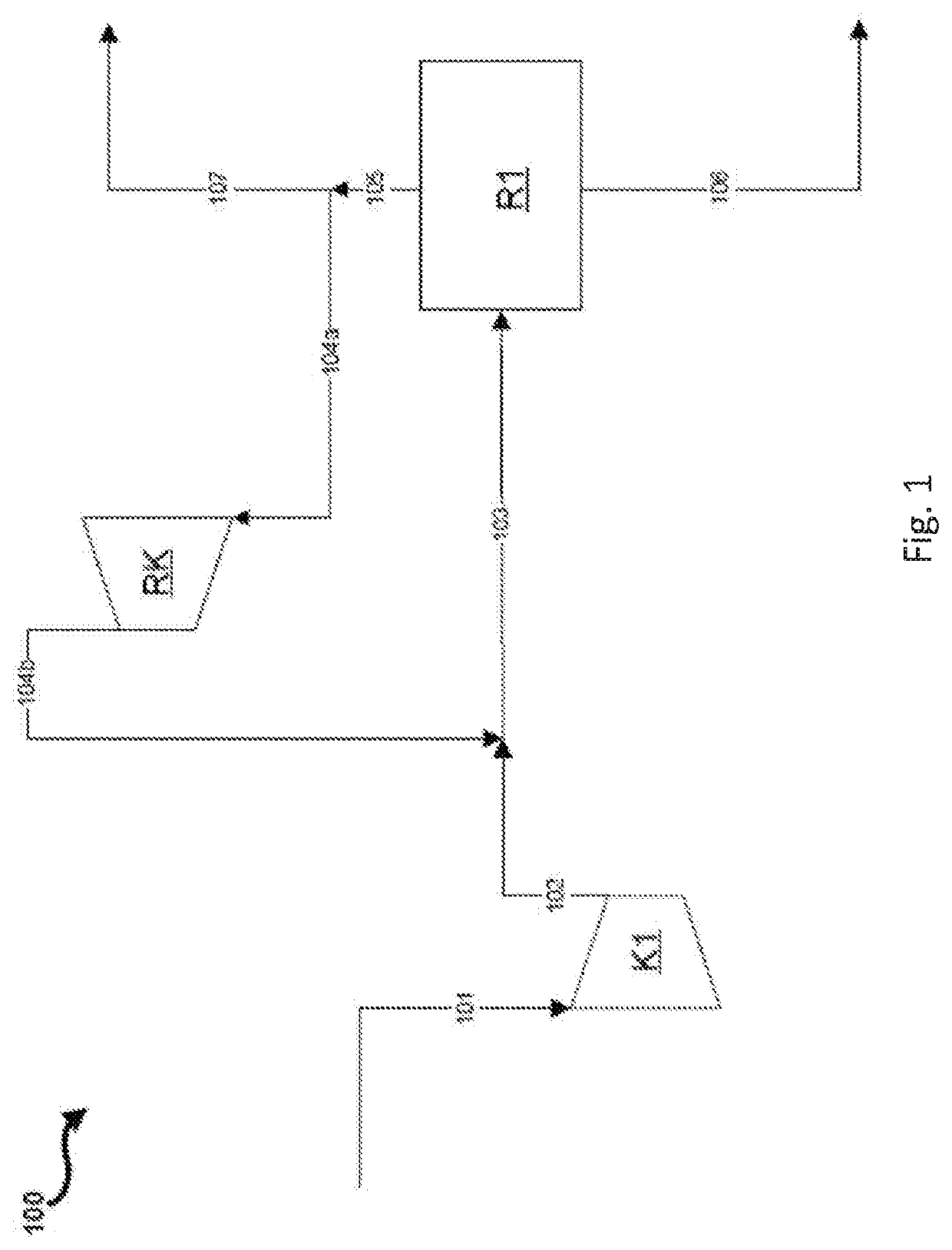
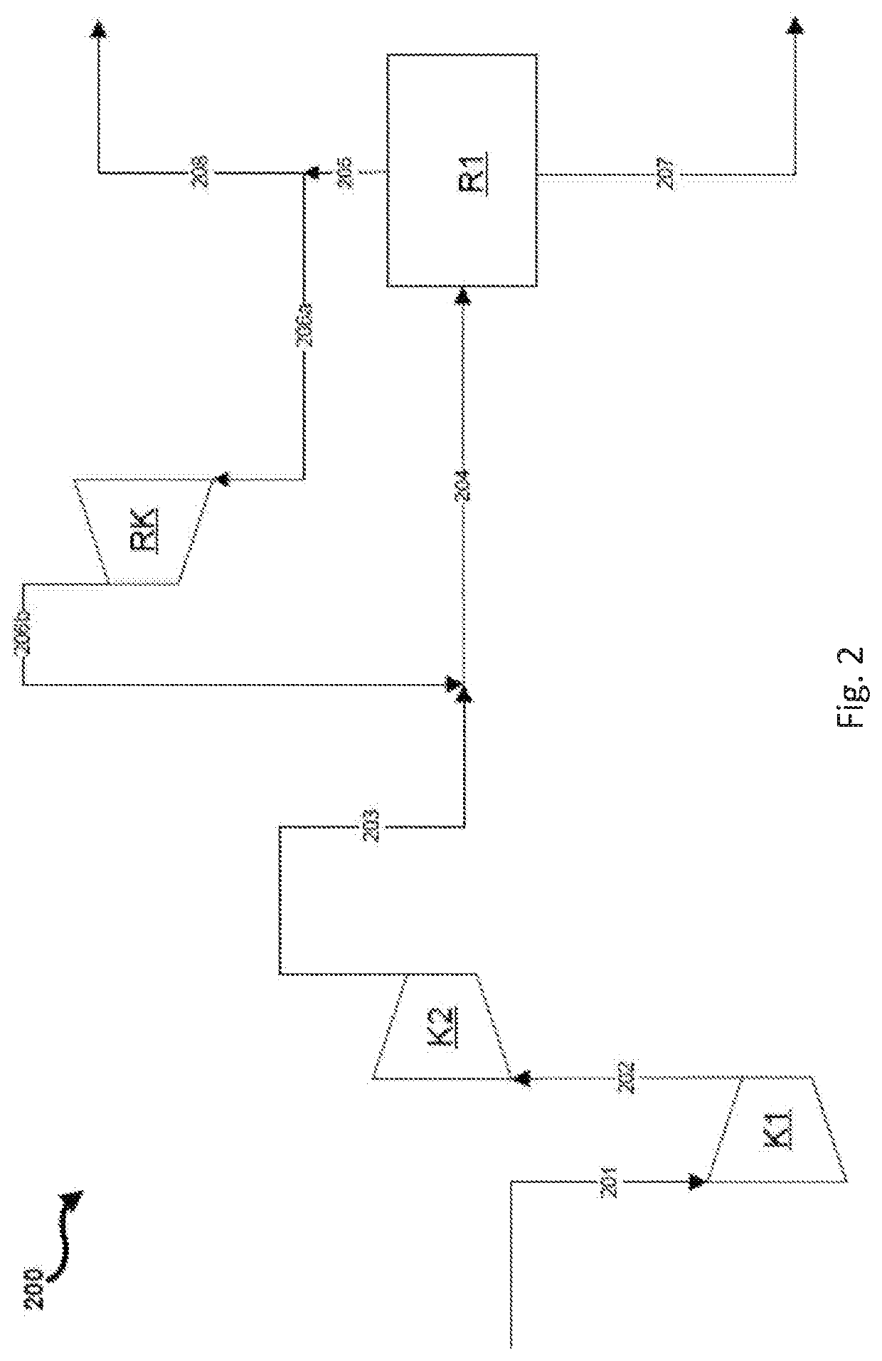
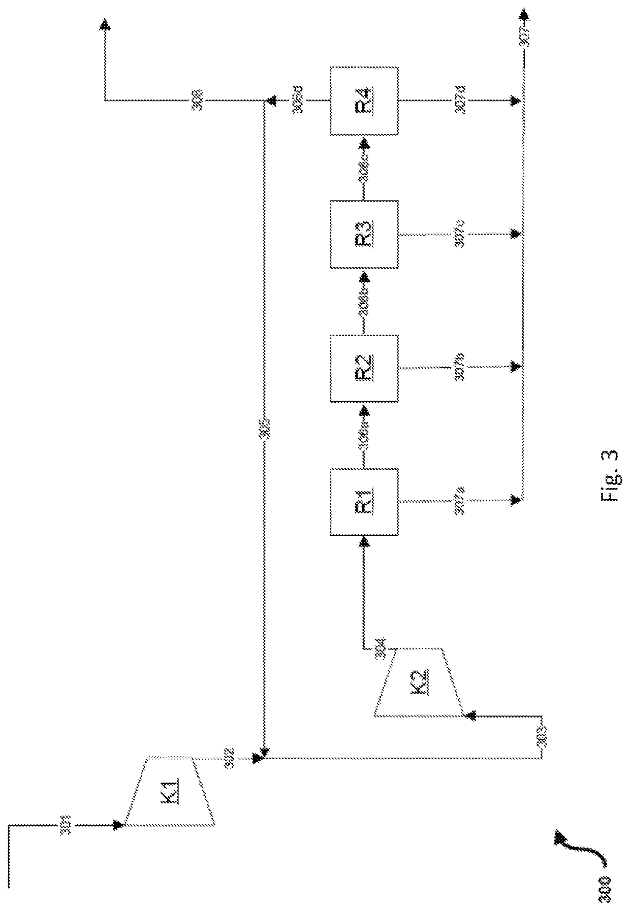
[0108]FIG. 1 shows a much simplified schematic block flow diagram of a production process for methanol comprising a recycle gas compressor stage in a synthesis circuit comprising a single reactor stage and a single compressor stage for fresh gas.

[0109]A first compressor stage K1 is supplied with a fresh gas stream 101 at a pressure of 34 bar. The fresh gas has a hydrogen proportion of 68.9% by volume, a carbon monoxide proportion of 18.9% by volume and a carbon dioxide proportion of 10.5% by volume. Due to the molar ratios of the fresh gas components the fresh gas for the fresh gas stream 101 has a stoichiometry number SN of 2.00. The fresh gas stream 101 is compressed by the first compressor stage K1, thus affording a second fresh gas stream 102 on the pressure side of the compressor stage K1. The second fresh gas stream 102 is combined with the recycle gas stream 104b; thus resulting in a combined gas stream referred to here as synthesis gas stream 103. The compression by compress...


PUM

PropertyMeasurementUnit
Percent by volumeaaaaaaaaaa
Volumeaaaaaaaaaa

Abstract

The invention relates to a process for producing methanol and to a plant for producing methanol. A first fresh gas suitable for production of methanol is precompressed by a first compressor stage to obtain a second fresh gas. The second fresh gas is merged with a recycle gas stream and further compressed to synthesis pressure in a second compressor stage. Catalytic conversion of the thus obtained synthesis gas stream in a plurality of serially arranged reactor stages with intermediate condensation and separation of the crude methanol reduces the recycle gas amount in the synthesis circuit to such an extent that recycle gas may be directly recycled to the second fresh gas stream, thus ensuring that no recycle gas compressor stage is required and that the total compressor power may be reduced.

Description

CROSS REFERENCE TO RELATED APPLICATIONS[0001]This application claims the benefit of priority under 35 U.S.C. § 119 (a) and (b) to European Patent Application No. 19020479.2, filed Aug. 19, 2019, the entire contents of which are incorporated herein by reference.BACKGROUNDField of the Invention[0002]The invention relates to a process for producing methanol, to a plant for producing methanol and to the use of the plant according to the invention in the process according to the invention.Prior Art[0003]Methanol is today typically produced by catalytic conversion of synthesis gas, a mixture of predominantly hydrogen (H2), carbon monoxide (CO) and carbon dioxide (CO2) in the so-called low-pressure process at pressures between 60 and 120 bar. Carbon monoxide and carbon dioxide may together also be referred to as “carbon oxides”.[0004]Depending on technology and plant capacity it is typically either single-stage or two-stage processes that are employed for conversion of the synthesis gas in...

Claims


Application Information

Patent Timeline
IPC IPC(8): C07C29/151B01J19/24
CPCC07C29/1516B01J19/245B01J2219/24B01J2219/00761B01J2219/00002B01J8/04C07C31/04C07C29/1518B01J12/007B01J2208/00628B01J2208/00017
Inventor SCHUHMANN, TIMM
Owner LAIR LIQUIDE SA POUR LETUDE & LEXPLOITATION DES PROCEDES GEORGES CLAUDE
Learn More