Method and system for classifying data objects based on their network footprint

a data object and network footprint technology, applied in the field of detecting new cyber threats, can solve the problems of high false alarm rate of anomaly based malware detection approach, insufficient customer side protection with static and dynamic analysis and anomaly detection, and inability to adapt to the growing cyber threat of cyber security solutions in the market, so as to improve protection, improve malware detection capabilities, and reduce detection time

Pending Publication Date: 2021-01-21
INTELICI CYBER DEFENSE SYST LTD
View PDF16 Cites 13 Cited by
  • Summary
  • Abstract
  • Description
  • Claims
  • Application Information

AI Technical Summary

Benefits of technology

The new malware detection technology aims to improve malware detection capabilities, reduce detection time, improve protection, and reduce infection for non-professionals. The method, in some cases, filters out new malwares based on their footprint, which can help shorten the detection time compared to commercial products. Additionally, the method may use filtering rules based on analyzing data from both internal and external sources to further filter out malicious objects. Overall, this technology aims to provide better protection against malicious software.

Problems solved by technology

The time required to generate signatures for new attacks varies between days to months due to the enormous numbers of new attacks.Private sector is less protected and thus is the incubator for most cyber-attacks.The Cyber Security solutions in the market are failing to adjust to the growing cyber threat.
The traditional approaches, such as customer side protection with static and dynamic analysis and anomaly detection are not sufficient for handling today's new threats which spawn in those regions of the Internet where costly cyber protection is not appreciated.The fundamental limitation of anomaly based malware detection approach is its high false alarm rate.
However, there are three common deficiencies in such methods: (1) Each one of these features is meant to capture a specific aspect of the network structure and, therefore, should be picked up manually by domain experts taking into account a specific application, in our case classification of objects contained in the communication traffic to malicious or benign based on their footprint in the traffic.
These features are limited in nature and cannot be claimed to cover all, or even most, of the network structure aspects.
But the normalisation methods affect the distance metric and may distort the results.
(3) Computation of some of the global features does not scale well.
Feature engineering is a tedious task that requires domain knowledge in order to construct meaningful features.
Even with feature generation techniques that recombine or aggregate topological features at various levels, there is no consensus on what is the best set of features for network comparison and classification.
So far, no research has introduced a covering set of global features.
Both graphlets and motifs have two important drawbacks: they are locally constrained and represent unlabelled and unweighted structural patterns.
This former drawback is especially apparent when looking at multiplex networks [19,20].
But small connected subgraphs such as graphlets or motifs do not capture relationships between communities or relationships between distant vertices.
These results suggest that trained Link Prediction models can be used to represent networks and collections of networks, however, these results were not leveraged for network classification on large scales.
This network matching process does not scale well.
It works for pattern graphs of objects extracted from images, but cannot withstand the scale of large networks.
The main challenge in applying standard neural networks on graph data is the ordering of vertices / edges.
The primary difficulties that hinder application of CNNs to subgraph classification are: (1) receptive fields contain a sequence of successive vertices according to the canonical labelling, while indicative patterns may be dispersed; (2) large receptive fields increase the computational effort of the approach, but small receptive fields will not capture global network properties such as the community structure; (3) the approaches described above cannot be trivially extended to classification of subgraphs in the context of larger networks.

Method used


Image

  • Method and system for classifying data objects based on their network footprint
  • Method and system for classifying data objects based on their network footprint
  • Method and system for classifying data objects based on their network footprint

Examples


Embodiment Construction

[0082]Before explaining at least one embodiment of the invention in detail, it is to be understood that the invention is not limited in its application to the details of construction and the arrangement of the components set forth in the following description or illustrated in the drawings. The invention is applicable to other embodiments or of being practiced or carried out in various ways. Also, it is to be understood that the phraseology and terminology employed herein is for the purpose of description and should not be regarded as limiting.

[0083]Definitions

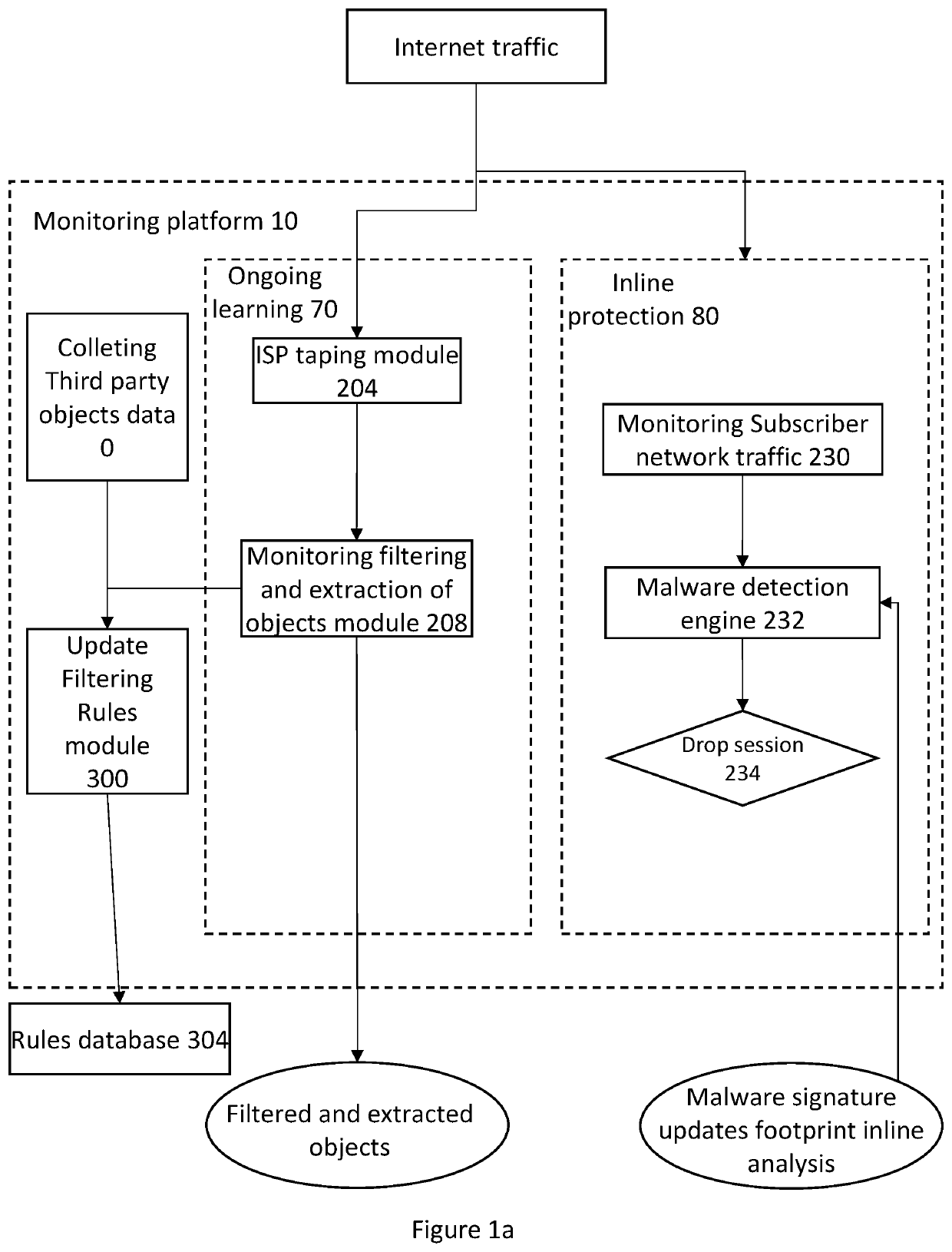
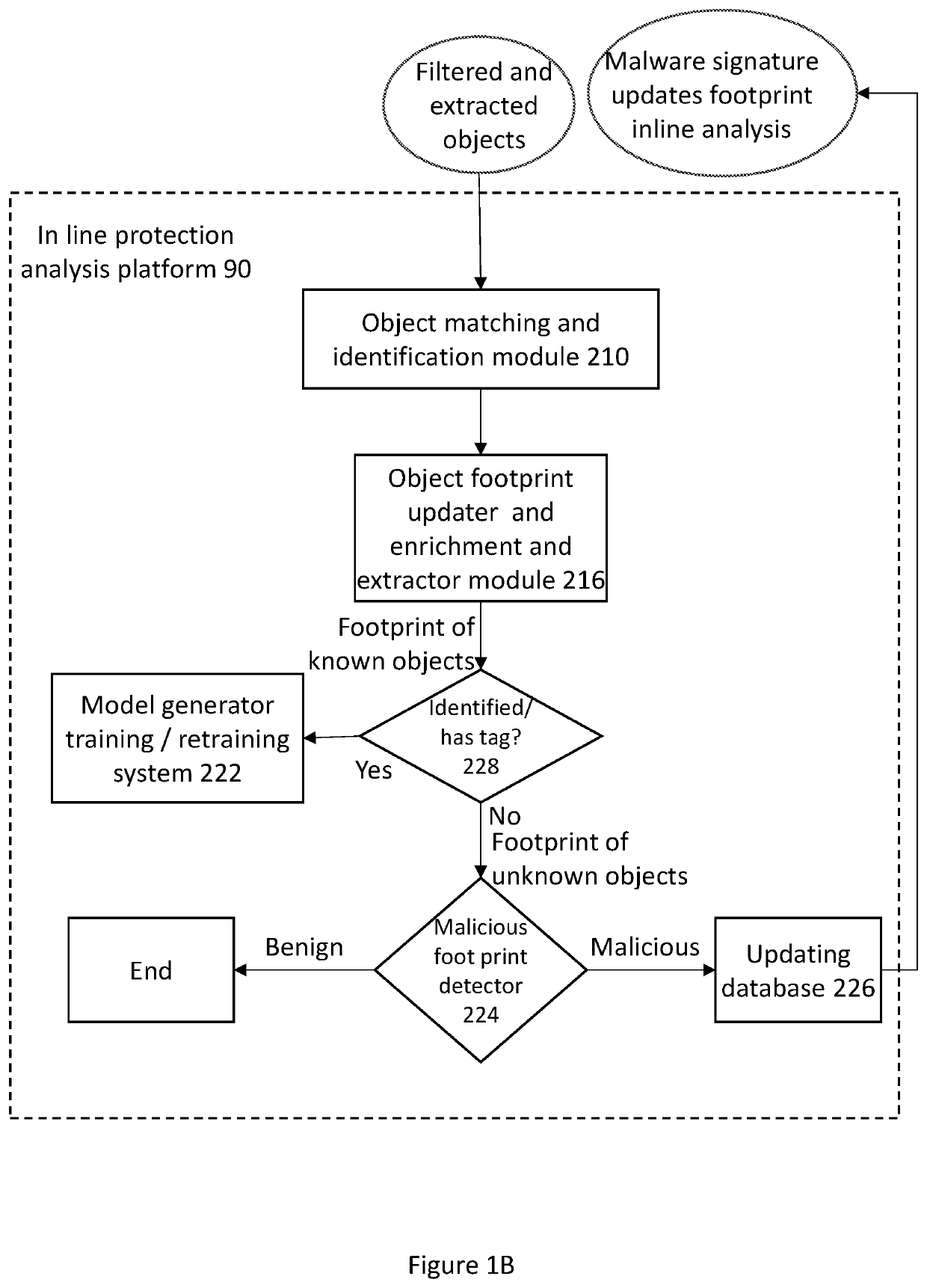
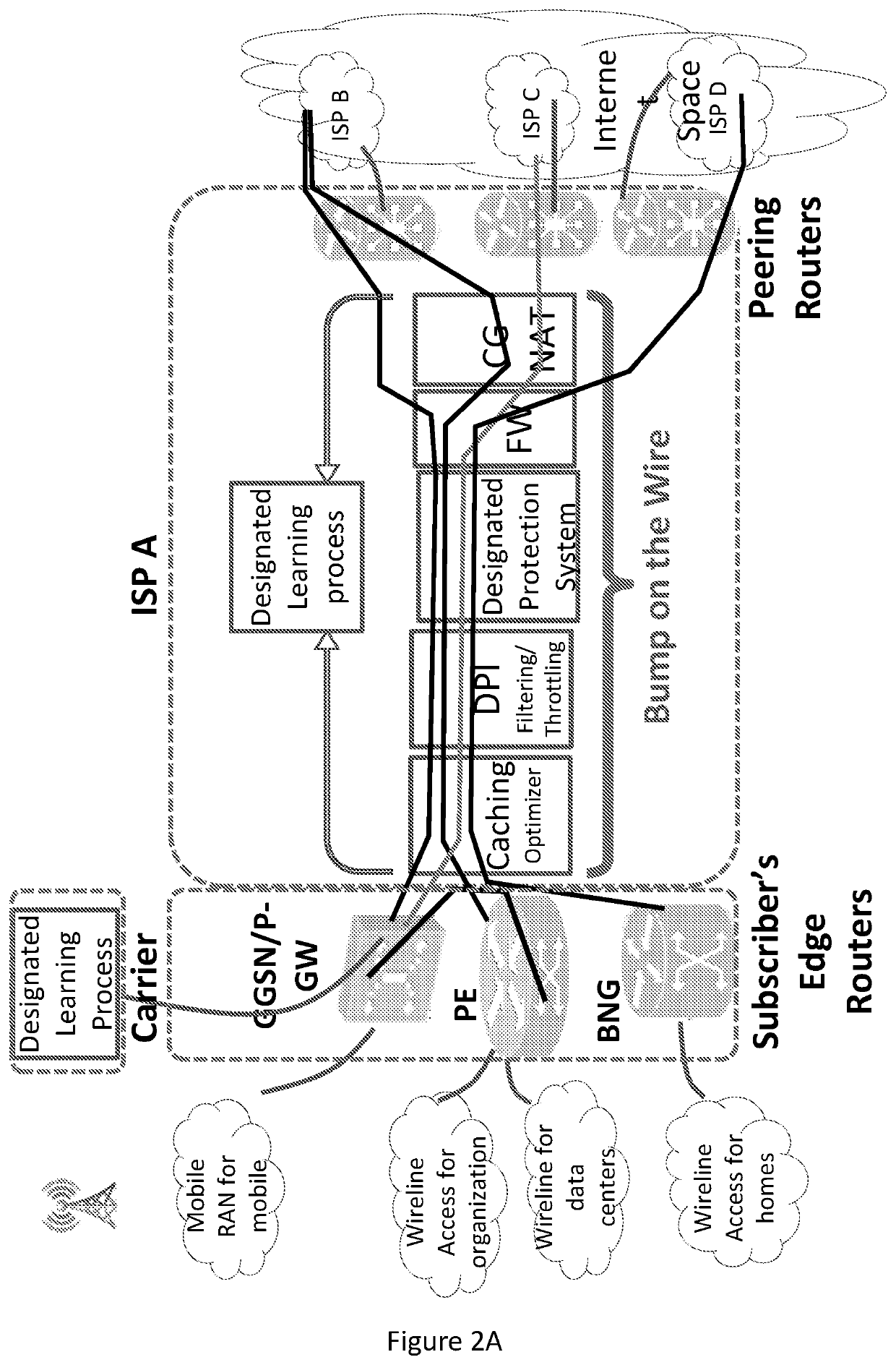
[0084]The term “Object” as referred in the present invention—may include any digital piece of information or software that can be replicated, stored on magnetic, optical or electronic storage, and transmitted through a communication network. Examples: an image in jpg format, an executable binary file, an HTTP request, Java scripts, and etc.

[0085]The term “Known object” as referred in the present invention define an object whic...


PUM


Abstract

The present invention provides a method for determining a type of an object distributed through communication network said method implemented by one or more processing devices operatively coupled to a non-transitory storage device, on which are stored modules of instruction code that when executed cause the one or more processing devices to perform: monitoring objects traffic through communication network; building the objects' footprint, wherein said footprint is inferred from monitored traffic flows that contain said object wherein the footprint is organized in a graph structure wherein nodes are source and target network addresses of said traffic flows two nodes are connected if there is a traffic flows between the network address of the respective nodes containing the said object, analyzing the objects footprint for identifying features characteristics / parameters of the footprint to determine the objects type.

Description

BACKGROUNDField of the Invention[0001]The present invention relates to the field of detecting new cyber threat by analyzing Objects propagation in ISP traffic using machine learning techniques. Using these techniques enables to detect unknown threats at early stage of the threat lifecycle and thus improve detection time and protect business, private networks, mobile customers, TOT networks, connected cars and more.Description of the Related Art[0002]The need:[0003]The number of new attacks is growing every day. The time required to generate signatures for new attacks varies between days to months due to the enormous numbers of new attacks.[0004]Private sector is less protected and thus is the incubator for most cyber-attacks.[0005]The Cyber Security solutions in the market are failing to adjust to the growing cyber threat. The traditional approaches, such as customer side protection with static and dynamic analysis and anomaly detection are not sufficient for handling today's new th...

Claims


Application Information

Patent Timeline
Patent Type & Authority Applications(United States)
IPC IPC(8): H04L29/06H04L12/24H04L12/26G06N20/00G06K9/62
CPCH04L63/1416H04L63/1425H04L41/14G06K9/6215H04L43/062G06N20/00H04L43/028H04L63/1408H04L63/145H04L41/142G06F18/22
Inventor SHABTAI, ASSAFLEVI, DRORISRAELI, ELADPUZIS, RAMI
Owner INTELICI CYBER DEFENSE SYST LTD
Why Eureka
Try Eureka