
Systems and methods for a composite solid-state battery cell with an ionically conductive polymer electrolyte

a solid-state battery cell and polymer electrolyte technology, applied in the field of solid-state battery cell systems and methods, can solve the problems of reducing the resistance of the electrolyte/separator layer, reducing the capacity, and poor performance, so as to prevent the occurrence of shorting, reduce the resistance of the electrode, and reduce the resistance. the effect of resistan

Pending Publication Date: 2021-01-07
A123 SYSTEMS LLC
View PDF2 Cites 4 Cited by
  • Summary
  • Abstract
  • Description
  • Claims
  • Application Information

AI Technical Summary

Benefits of technology

The patent text describes a method for designing a dense structure with a population of particulate materials, including electrode active materials, solid polymer electrolyte, conducting additives, binder, and other organic and inorganic components of a functional or passive nature. The inventors have determined that the particle size distributions and relative percentages of the individual components should be carefully selected to optimize the inter-particle packing and the functionality of the component materials. The process of combining the components should also be carefully considered as it can influence the size and distribution of the materials in the composite form. The unique functionality of the separator dictates a different set of design criteria to provide low resistance to lithium transport between electrodes while also serving as a mechanical barrier to prevent shorting. The resistance to lithium migration can be reduced by increasing the contact area between the electrode layers and the electrolyte, as well as reducing the thickness of the electrolyte layers. The method also includes differential tuning of the size distributions and relative fractions of component materials in the electrode and electrolyte layers to further optimize the structure. The coated electrode structure formed using this method has reduced porosity, improved percolation networks, reduced resistance to lithium transport, and improved mechanical stability in a battery cell.

Problems solved by technology

Furthermore, the packing efficiency of the materials including the energy storage device influence the energy density whereby inefficiencies are realized in the form of porosity or free volume, which for a given capacity, manifests in the form of increased volume, or in the case of fixed volume, results in decreased capacity.
With increasing internal resistance the power characteristics of a battery diminish leading to poor performance when high charge or discharge rates are required.
While this medium of ion transport provides high levels of mobility for the lithium ions, it presents the disadvantage of being highly flammable, resulting in safety concerns in the context of automotive or other transport applications.
Additionally, configuration of particles forming the electrolyte layer so as to reduce the tortuosity of the path the lithium ions follow from one electrode to another may decrease the resistance of the electrolyte / separator layer.
In addition to identifying methods of manufacturing that accommodate this required flexibility, significant tuning of the parameters defining how each of these techniques is deployed constitutes a significant and non-intuitive challenge to the practitioner tasked with the manufacturing of solid state batteries therefrom.

Method used


Image

  • Systems and methods for a composite solid-state battery cell with an ionically conductive polymer electrolyte
  • Systems and methods for a composite solid-state battery cell with an ionically conductive polymer electrolyte
  • Systems and methods for a composite solid-state battery cell with an ionically conductive polymer electrolyte

Examples


Embodiment Construction

[0033]The following description relates to systems and methods for a solid-state battery cell including an ionically conductive polymer material as an electrolyte. Specifically, the ionically conductive polymer material may be a solid ionically conducting powder, such as the solid, ionically conductive polymer material U.S. Patent Application Publication No. 2017 / 0018781, International Patent Publication No. 2016 / 196873, and U.S. Patent Application Publication No. 2017 / 0005356 the contents of which are incorporated herein by reference, and such as the solid ionically conducting powder produced by Ionic Materials Inc. of Woburn, Mass. The solid ionically conductive polymer material may be synthesized from: a polymer, a dopant and an ionic compound. The base polymer may be semicrystalline or fully crystalline. Typical materials that may be used for the base polymer include liquid crystal polymers and polyphenylene sulfide, also known as PPS, or a semi-crystalline polymer with a crysta...


PUM

PropertyMeasurementUnit
ionic conductivityaaaaaaaaaa
d50 particle sizeaaaaaaaaaa

Abstract

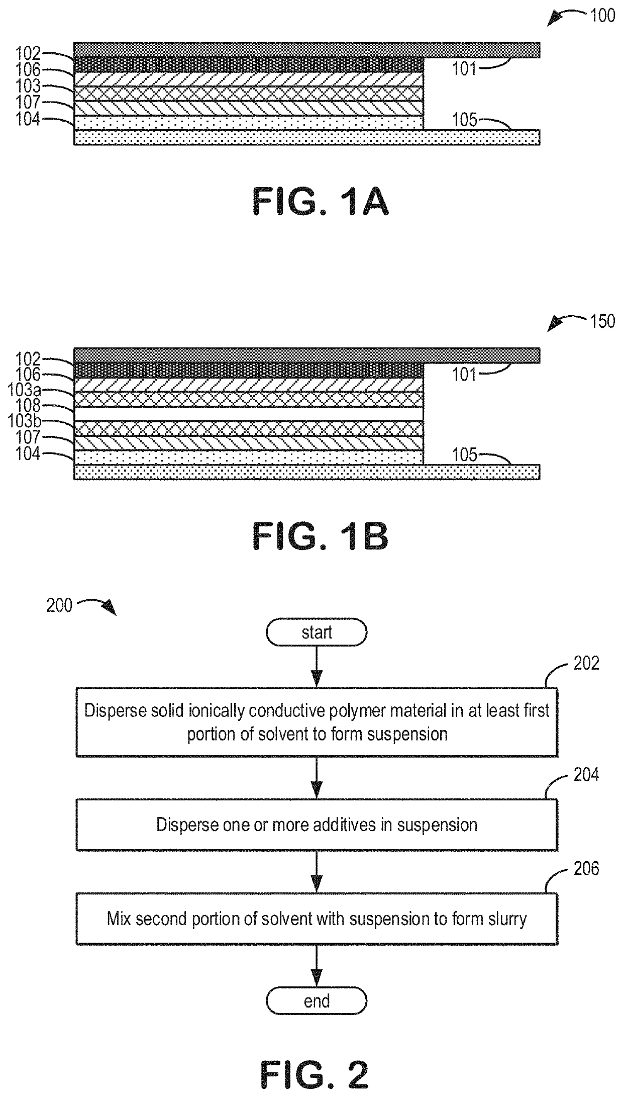
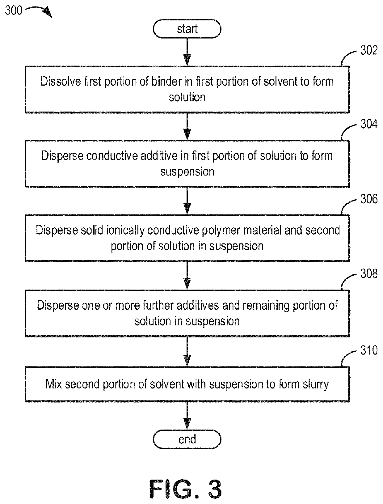
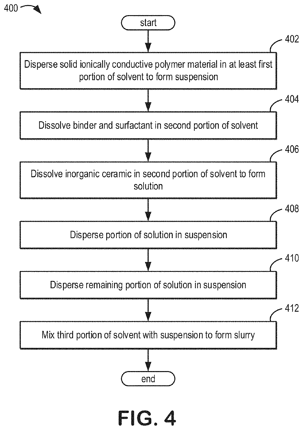
Systems and methods are provided for a slurry for coating an electrode structure. In one example, a method may include dispersing, by mixing at one or both of a high shear and a low shear, a solid ionically conductive polymer material in at least a first portion of a solvent to form a suspension, then dispersing, by mixing at the one or both of the high shear and the low shear, one or more additives in the suspension, and then mixing, at the one or both of the high shear and the low shear, a second portion of the solvent with the suspension to form a slurry. As such, the slurry including the solid ionically conductive polymer material may be applied as a coating in a solid-state battery cell, which may reduce resistance to Li-ion transport and improve mechanical stability relative to a conventional solid-state battery cell.

Description

CROSS REFERENCE TO RELATED APPLICATIONS[0001]The present application claims priority to U.S. Provisional Application No. 62 / 869,407, entitled “SYSTEMS AND METHODS FOR A COMPOSITE SOLID-STATE BATTERY CELL WITH AN IONICALLY CONDUCTIVE POLYMER ELECTROLYTE,” and filed on Jul. 1, 2019. The entire contents of the above-identified application are hereby incorporated by reference for all purposes.FIELD[0002]The present description relates generally to systems and methods for a solid-state battery cell including an ionically conductive polymer material.BACKGROUND AND SUMMARY[0003]The energy density of a secondary battery is an important figure of merit as it describes how much work can be performed per unit mass or volume when calculated in gravimetric or volumetric terms, respectively. In the context of automotive applications these measures matter as they dictate the distance a car can travel before requiring charging relative to how much of the car's total mass or volume is dedicated to t...

Claims


Application Information

Patent Timeline
Patent Type & Authority Applications(United States)
IPC IPC(8): H01M10/0565H01M10/0585H01M4/04H01M4/62
CPCH01M10/0565H01M10/0585H01M4/0404H01M2004/021H01M4/0435H01M4/62H01M2300/0082H01M4/0471H01M10/052H01M4/622H01M4/139H01M2300/0065Y02E60/10
Inventor HOFFERT, WESLEYROJAS, ADRIANA A.LAUGHMAN, DAVID M.BUANNIC, LUCIENNEJOHNSON, DEREK C.SISK, BRIANCHIOU, BRIANGILLOOLY, THOMAS
Owner A123 SYSTEMS LLC
Learn More