Automated polarization control

Active Publication Date: 2020-10-08
CANON USA
View PDF0 Cites 1 Cited by
  • Summary
  • Abstract
  • Description
  • Claims
  • Application Information

AI Technical Summary

Benefits of technology

The present patent is related to an optical receiver that optimizes polarization diversity and balanced detection for improved image quality. This can be achieved via motorized controls that automatically adjust the optical receiver to improve interfering signals. The patent also discusses a method of low-pass filtering a polarization error signal to provide advantages such as no need for high speed data acquisition, no need to synchronize the micro-controller, and polarization control is decoupled from the main OCT data acquisition board. Additionally, the patent describes how the polarization control procedure achieves greater processing speed and accuracy, monitors the error signal in real-time, and alerts and corrects any polarization issues. Balanced detection is also achieved by splitting light and feeding it to a balanced photodetector or detectors to reduce noise. The patent also mentions that the size of the optical apparatus or system can be reduced, and it can acquire black and white or color images based on the specified location of the pullback.

Problems solved by technology

More often, one ends up with a situation where the two electromagnetic waves do interfere but not efficiently because the polarizations are mis-aligned.
In such a case, some of the interfering signal is lost.
However, an issue arises in a lack of clarity regarding how to best select polarization axes or achieve polarization diversity.
Another issue arises in providing optical receivers with balanced detection.
However, a lack of clarity exists regarding how to best achieve balanced detection.
Previous optical receivers, and controllers for same, also fail to address any potential disturbances, such as, but not limited to, polarization drift over time, temperature and / or mechanical perturbations or variations.

Method used


Image

  • Automated polarization control
  • Automated polarization control
  • Automated polarization control

Examples


Embodiment Construction

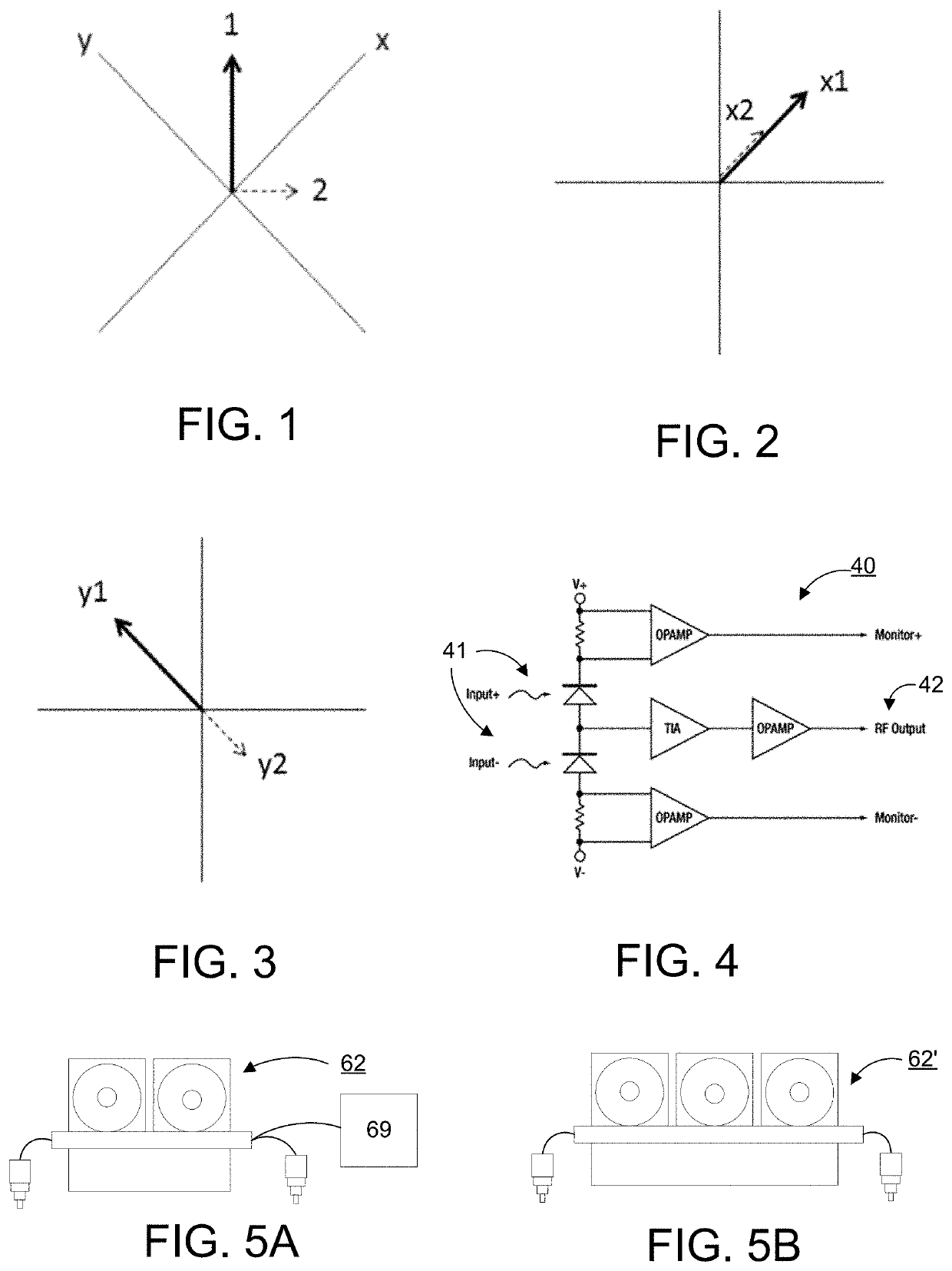
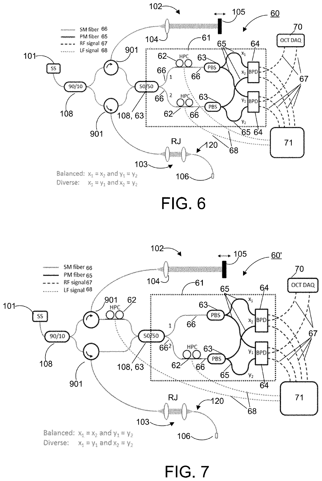
[0052]Embodiments will be described below with reference to the attached drawings. Like numbers refer to like elements throughout. It shall be noted that the following description is merely illustrative and exemplary in nature, and is in no way intended to limit the disclosure and its applications or uses. The relative arrangement of components and steps, numerical expressions and numerical values set forth in the embodiments do not limit the scope of the disclosure unless it is otherwise specifically stated. Techniques, methods, and devices which are well known by individuals skilled in the art may not have been discussed in detail since an individual skilled in the art would not need to know these details to enable the embodiments discussed below. Further, an endoscope as disclosed in the following which is used to inspect an inside a human body may also be used to inspect other objects. Examples of specialized endoscopes which are examples of endoscope in which an embodiment may ...


PUM


Abstract

One or more devices, systems, methods and storage mediums for optical imaging medical devices, such as, but not limited to, Optical Coherence Tomography (OCT), single mode OCT, and / or multi-modal OCT apparatuses and systems, and methods and storage mediums for use with same, for performing automated polarization control, polarization diversity and / or balanced detection are provided herein. One or more embodiments may achieve polarization diversity and balanced detection (or photo-detection) under any imaging circumstances. One or more embodiments, may achieve polarization control functionality regardless of whether such control is automatic or manual. Additionally, one or more embodiments may achieve automated polarization control, may achieve balanced detection (or photo-detection), and / or may address potential disturbances, such as, but not limited to, polarization drift over time, temperature and / or mechanical perturbations or variations. One or more embodiments may include an optical receiver where polarization diversity and balanced detection may be optimized via motorized controls.

Description

CROSS-REFERENCE TO RELATED APPLICATION(S)[0001]This application relates, and claims priority, to U.S. Patent Application Ser. No. 62 / 831,032, filed Apr. 8, 2019, the entire disclosure of which is incorporated by reference herein in its entiretyFIELD OF THE DISCLOSURE[0002]The present disclosure relates generally to the field of medical imaging and processing medical image data, and more particularly to apparatuses, systems, and methods and storage mediums for use therewith, that perform automated polarization control, polarization diversity and / or balanced detection.BACKGROUND OF THE DISCLOSURE[0003]Optical coherence tomography (OCT) is a technique for obtaining high resolution cross-sectional images of tissues or materials, and enables real time visualization. The aim of the OCT techniques is to measure the time delay of light by using an interference optical system or interferometry, such as via Fourier Transform or Michelson interferometers. A light from a light source delivers a...

Claims


Application Information

Patent Timeline
IPC IPC(8): G01B9/02
CPCG01B9/02009G01B9/02044A61B3/102G01B9/02091G01B2290/45G01B2290/70G01B9/02068G01B9/02041G01B9/02004
Inventor ELMAANAOUI, BADRPIAS, MATTHEW SCOTTMABBOUX, PIERRE-YVES
Owner CANON USA
Why Eureka
Try Eureka