
Methanol production process

a methanol production and process technology, applied in the field of methanol production process, can solve the problems of reducing the use of rwgs

Active Publication Date: 2020-07-02
FUNDACIO INST CATALA DINVESTIGACIO QUIMICA
View PDF0 Cites 1 Cited by
  • Summary
  • Abstract
  • Description
  • Claims
  • Application Information

AI Technical Summary

Benefits of technology

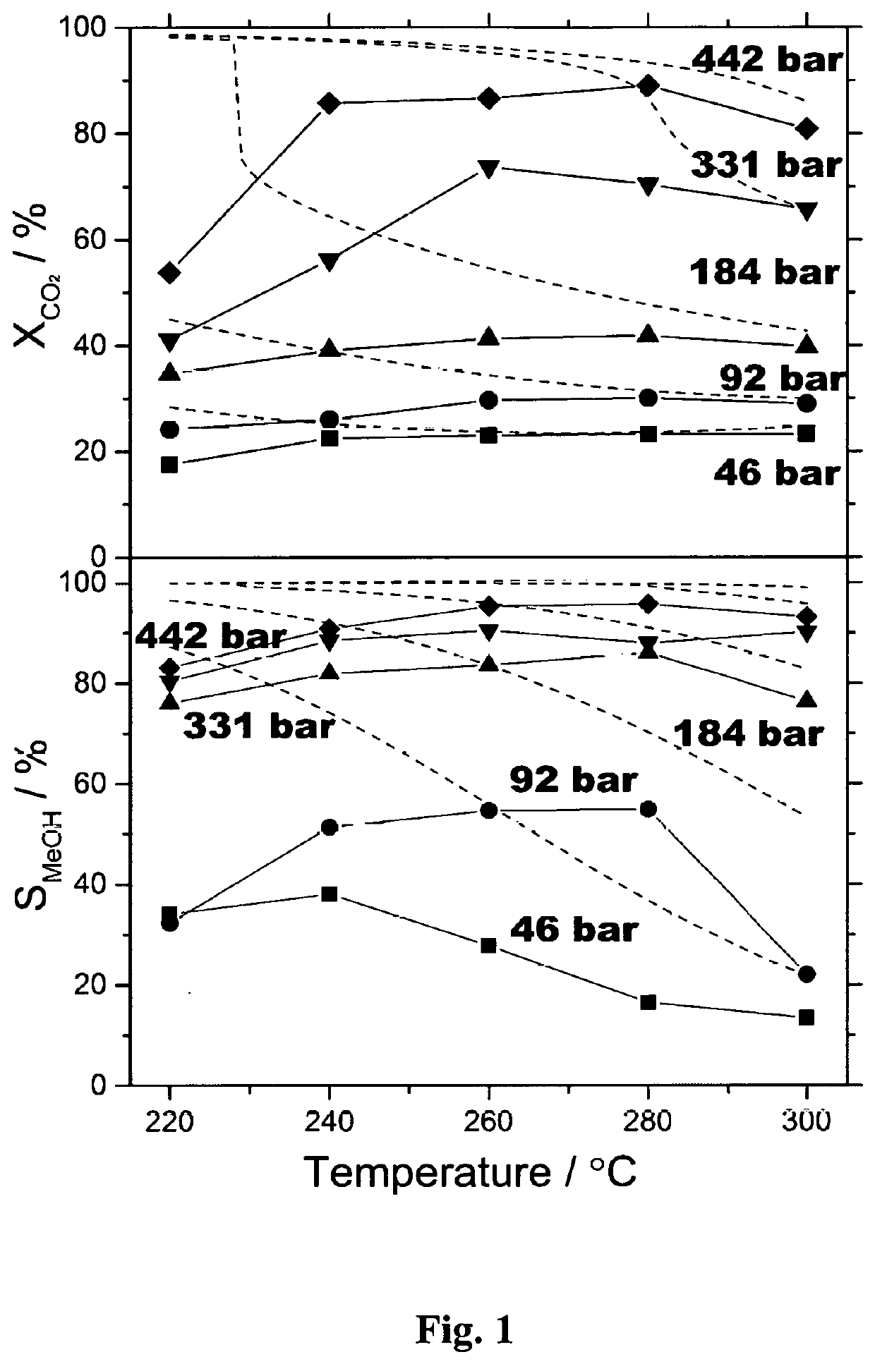
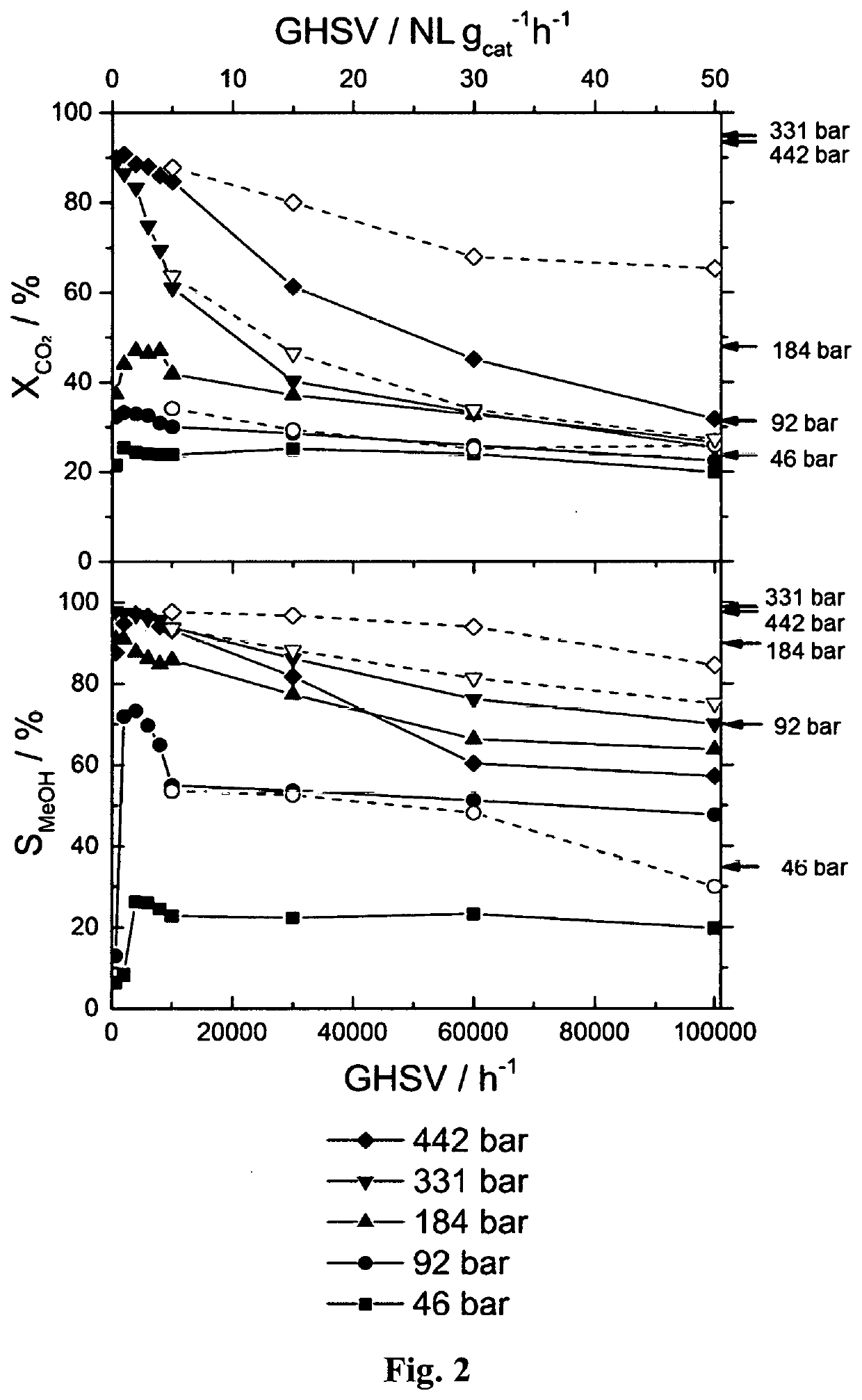
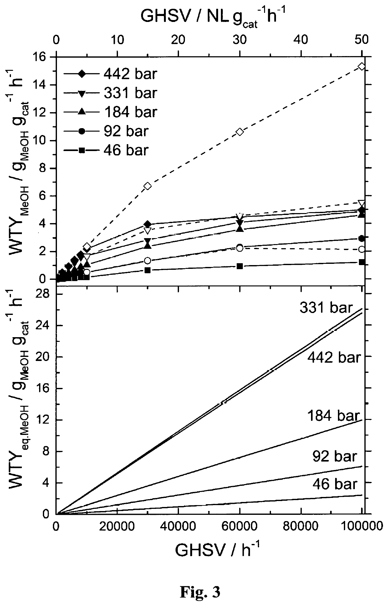
The invention provides a process for producing methanol by the stoichiometric hydrogenation of carbon dioxide using a copper / zinc oxide catalyst with a high specific copper surface area. The process can achieve outstanding CO2 conversions and methanol selectivities at a stoichiometric ratio of CO2 to H2 of 1:3. The high space velocities and high weight time yields of methanol can be achieved under particular high-pressure conditions. The process is highly productive for methanol and ensures a high proportion of active sites in the accessible diffusion layer of the catalyst. The invention also provides a method for synthesizing methanol at very high space velocities and high weight time yields.

Problems solved by technology

The ever-increasing energy demand to sustain industrialization and modern lifestyle has led to depletion consumption of the world's current primary energy supply, finite and non-renewable fossil fuels.
In parallel, their irreversible consumption has resulted in accumulation of carbon dioxide (CO2) in the atmosphere, causing the climate to change.
However, despite the exceptionally high CO2 conversion and methanol selectivity under high-pressure conditions and also high process viability in terms of costs and methanol productivity, the reported reaction condition requires recycling or further conversion of unreacted H2 fed in excess.
In addition, the CO produced by RWGS needs to be recycled if methanol selectivity is not sufficiently high.
In other words, the challenge in this respect is to achieve complete conversion of both CO2 and H2 with high methanol productivity, leaving little or no CO in the product stream.
A key challenge therefore remains, to increase the productivity of methanol by the reaction between H2 and CO2, whilst at the same time avoiding the need to recycle H2 and minimising CO produced by RWGS.

Method used


Image

  • Methanol production process
  • Methanol production process
  • Methanol production process

Examples


example 1

Experimental Procedure

[0145]A continuous flow, high-pressure fixed-bed reactor was used to study the hydrogenation of CO2 to methanol. The reactor made of stainless steel was in a tubular shape with outer diameter of ⅛″ or ¼″ with inner diameter of 0.07″ or 0.12″, respectively. The details of high-pressure fixed-bed reactor and analytical systems are described in A. Bansode, B. Tidona, P. R. von Rohr, A. Urakawa, Catal. Sci. Technol., 3 (2013) 767-778. The reactant gas mixture (molar ratio of CO2:H2:Ar=23:69:8) was purchased from Abelló Linde (Spain). A commercial methanol synthesis catalyst (Cu / ZnO / Al2O3, Product No.: 45776) was purchased from Alfa Aesar. The catalyst pellet was crushed, sieved to particle size of 100-300 μm, and charged to the reactor with approximate catalytic bed length of 20-100 mm depending on the amount of catalyst defined by the desired reaction conditions. Prior to the reaction, the catalyst was reduced in hydrogen stream (molar ratio of H2:Ar=90:10) at 20 ...


PUM

PropertyMeasurementUnit
Temperatureaaaaaaaaaa

Abstract

The invention provides a process for producing methanol, which process comprises contacting H2 and CO2 with a solid catalyst, at a temperature of from 200° C. to 300° C. and at a reactant pressure of from 150 bar to 500 bar, which reactant pressure is the sum of the partial pressures of the H2 and the CO2, wherein: the molar ratio of the H2 to the CO2 is x:1.0, wherein x is from 2.5 to 3.5; and the catalyst comprises: (i) a copper component which is Cu, CuO or Cu2O, or a mixture of two or three thereof, and (ii) ZnO, wherein the catalyst has a specific copper surface area of at least 10 m2 / g-catalyst.

Description

FIELD OF THE INVENTION[0001]The invention relates to a process for producing methanol.BACKGROUND TO THE INVENTION[0002]The ever-increasing energy demand to sustain industrialization and modern lifestyle has led to depletion consumption of the world's current primary energy supply, finite and non-renewable fossil fuels. In parallel, their irreversible consumption has resulted in accumulation of carbon dioxide (CO2) in the atmosphere, causing the climate to change. For sustainable development of mankind, the carbon cycle has to be closed; conversion of CO2 into chemical fuels and feedstocks serves as an effective strategy to cope with the interrelated energetic and environmental problems (M. Mikkelsen, M. Jorgensen, F. C. Krebs, Energ. Environ. Sci., 3 (2010) 43-81). Heterogeneous catalytic conversion of CO2 to fuels and industrially important chemicals, such as methanol, by the hydrogenation reaction, offers a unique path to transform a large amount of CO2 in a short span of time by ...

Claims


Application Information

Patent Timeline
IPC IPC(8): C07C29/154B01J23/06B01J23/72B01J35/02B01J35/10
CPCB01J35/023C07C29/154C07C31/04B01J23/72B01J35/1014B01J23/06Y02P20/52C07C29/151B01J35/40B01J35/613
Inventor URAKAWA, ATSUSHIBANSODE, ATULGAIKWAD, ROHIT VILAS
Owner FUNDACIO INST CATALA DINVESTIGACIO QUIMICA
Learn More