
High frequency based beamforming antenna and communication method therefor

a beamforming antenna and high frequency technology, applied in the field of integrated circuit millimeter wave and terahertz beaming antennas and communication methods using the same, can solve problems such as additional losses, and achieve the effects of reducing costs, reducing transmission losses, and increasing process efficiency

Active Publication Date: 2020-05-28
ELECTRONICS & TELECOMM RES INST
View PDF0 Cites 4 Cited by
  • Summary
  • Abstract
  • Description
  • Claims
  • Application Information

AI Technical Summary

Benefits of technology

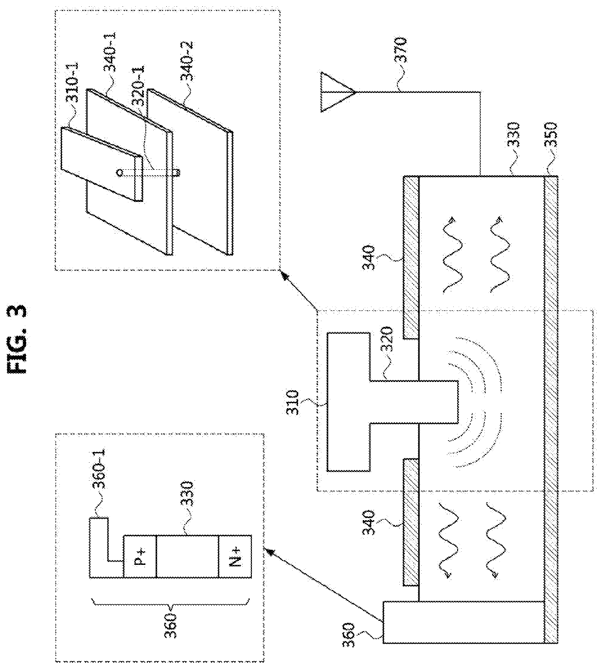
This patent pertains to a method of manufacturing an antenna unit and RF module using a single process, reducing cost and increasing efficiency. The method also minimizes signal transmission loss by feeding the RF module output signal directly into the antenna through an integrated circuit antenna that supports beamforming in the high frequency band. Additionally, the method maximizes the antenna's reflection efficiency and interference with existing signals using a semiconductor diode formed inside the antenna's semiconductor waveguide.

Problems solved by technology

However, these semiconductor antennas not only require complicated impedance matching parts for being connected with a radio frequency (RF) module, but also cause additional losses.

Method used


Image

  • High frequency based beamforming antenna and communication method therefor
  • High frequency based beamforming antenna and communication method therefor
  • High frequency based beamforming antenna and communication method therefor

Examples


Embodiment Construction

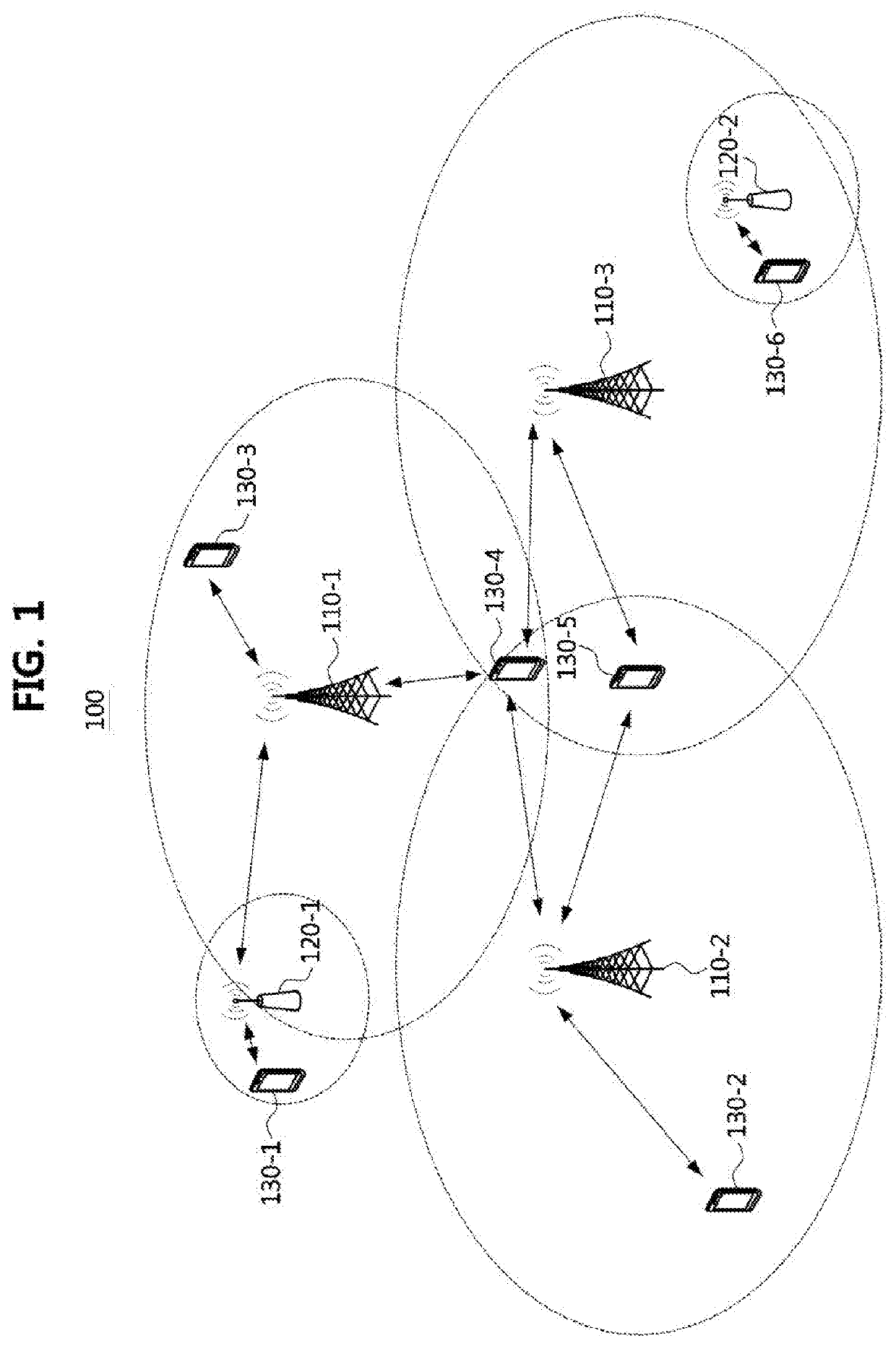
[0038]While the present invention is susceptible to various modifications and alternative forms, specific embodiments are shown by way of example in the drawings and described in detail. It should be understood, however, that the description is not intended to limit the present invention to the specific embodiments, but, on the contrary, the present invention is to cover all modifications, equivalents, and alternatives that fall within the spirit and scope of the present invention.

[0039]Although the terms “first,”“second,” etc. may be used herein in reference to various elements, such elements should not be construed as limited by these terms. These terms are only used to distinguish one element from another. For example, a first element could be termed a second element, and a second element could be termed a first element, without departing from the scope of the present invention. The term “and / or” includes any and all combinations of one or more of the associated listed items.

[004...


PUM


Abstract

A method for transmitting signals using a high frequency based integrated circuit beamforming antenna is disclosed. The method may comprise transferring an output signal of a radio frequency (RF) module to an RF transceiving unit; transferring an output signal of the RF transceiving unit to a signal converting unit including a feeding pillar; and transferring a wave signal from the signal converting unit to a traveling wave antenna unit, and the feeding pillar may convert the output signal of the RF transceiving unit to the wave signal.

Description

CROSS-REFERENCE TO RELATED APPLICATIONS[0001]This application claims priority to Korean Patent Application No. 10-2018-0147917 filed on Nov. 27, 2018 in the Korean Intellectual Property Office (KIPO), the entire contents of which are hereby incorporated by reference.BACKGROUND1. Technical Field[0002]The present disclosure relates to a structure of a super high frequency (SHF) or extremely high frequency (EHF) antenna and a communication method using the same, and more particularly, to an integrated-circuit millimeter wave and terahertz beaming antenna and a communication method using the same.2. Related Art[0003]The fifth generation mobile communication aiming at Gbps (giga bps) class support, which is at least 10 to 100 times higher data rate than that of 4th generation mobile communication, is expected to be implemented in a Giga Hertz (GHz) frequency band. Further, the sixth generation mobile communication is expected to be implemented in a frequency band of several hundred GHz (...

Claims


Application Information

Patent Timeline
IPC IPC(8): H04B3/52H04B7/06H01P3/16H01Q1/38H01Q21/06H01Q21/00H01Q3/36H01L23/66
CPCH01Q21/0037H01Q3/36H04B3/52H01Q1/38H04B7/0617H01Q21/065H01L23/66H01P3/16H01Q21/062H01Q1/2283H01Q21/20H01L2223/6677H01L2223/6627Y02D30/70H01Q3/26
Inventor CHO, YOUNG KYUNLEE, JUNG NAM
Owner ELECTRONICS & TELECOMM RES INST
Learn More