
Display panel and manufacturing method thereof

Pending Publication Date: 2020-04-02
WUHAN CHINA STAR OPTOELECTRONICS TECH CO LTD
View PDF0 Cites 3 Cited by
  • Summary
  • Abstract
  • Description
  • Claims
  • Application Information

AI Technical Summary

Benefits of technology

The patent describes a method of making a fingerprint sensor using a thin film transistor and an amorphous silicon photodiode on a glass substrate. This method results in a better signal to noise ratio and lower leakage current, and can be done using simple processes without additional complicated structures. The key technical effect is the simultaneous preparation of both the thin film transistor and the amorphous silicon photodiode.

Problems solved by technology

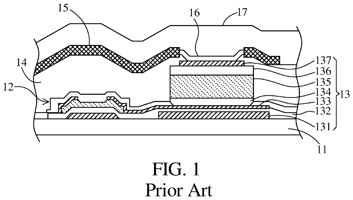
The optical path of the incident light in the pixel unit of the panel detector is long, and the incident light easily enters adjacent pixel units to cause interference.
Moreover, the amorphous silicon photodiode 13 needs to be separately fabricated after forming the thin film transistor 12, and multiple steps of film formation and lithography are required during the fabrication process so that production cost higher.

Method used


Image

  • Display panel and manufacturing method thereof
  • Display panel and manufacturing method thereof
  • Display panel and manufacturing method thereof

Examples


Embodiment Construction

[0035]Structure and technical means adopted by the present disclosure to achieve the above and other objects can be best understood by referring to the following detailed description of the preferred embodiments and the accompanying drawings. Furthermore, directional terms described by the present disclosure, such as upper, lower, front, back, left, right, inner, outer, side, longitudinal / vertical, transverse / horizontal, etc., are only directions by referring to the accompanying drawings, and thus the used directional terms are used to describe and understand the present disclosure, but the present disclosure is not limited thereto.

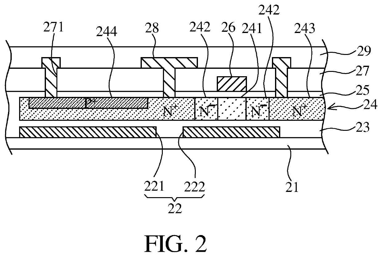
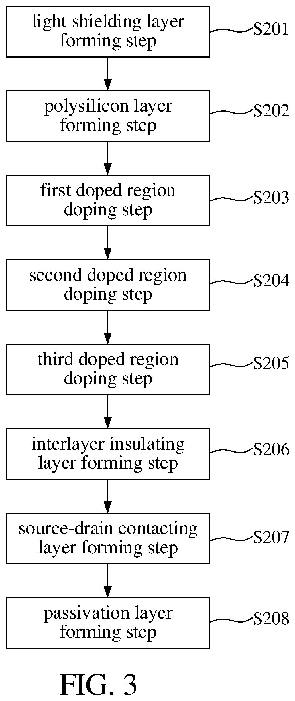
[0036]Referring to FIG. 2, a schematic diagram of a display panel according to a preferred embodiment of the present disclosure is illustrated. The display panel comprises a glass substrate 21, a light shielding layer 22, an insulating layer 23, a polysilicon layer 24, a gate insulating layer 25, a gate layer 26, an interlayer insulating layer 27, a sourc...


PUM


Abstract

A display panel and a manufacturing method thereof are provided. The display panel comprises a glass substrate, an insulating layer, a polysilicon layer, a gate insulating layer, a gate layer, an interlayer insulating layer, and a source-drain contacting layer, wherein the polysilicon layer is defined with a first doped region, a second doped region, and a third doped region. The source-drain contacting layer contacts the first doped region and the third doped region. A doping type of the first doped region and a doping type of the third doped region are different so that the first doped region and the third doped region form a PN structure. Doping type of the first doped region and a doping type of the second doped region are same.

Description

FIELD OF INVENTION[0001]The present disclosure relates to a display panel and a manufacturing method thereof, and in particular to a display panel for touchscreen and a manufacturing method thereof.BACKGROUND OF INVENTION[0002]In the prior art, a medical amorphous silicon panel detector is a conventional optical sensor, which comprises amorphous silicon photodiodes and thin film transistors. As shown in FIG. 1, a schematic diagram of a panel detector pixel unit is illustrated, wherein pixel units are formed on a substrate 11. Each of the pixel units comprises a thin film transistor 12 and an amorphous silicon photodiode 13, wherein the amorphous silicon photodiode 13 includes a first light shielding layer 131, a first insulating layer 132, a drain electrode layer 133, an N-type layer 134, an intermediate layer 135, a P-type layer 136 and a contact electrode 137.[0003]Furthermore, an insulating layer 14 insulates the thin film transistor 12 from the amorphous silicon photodiode 13. A...

Claims


Application Information

Patent Timeline
IPC IPC(8): G06F3/042G06F3/041G06K9/00H01L31/10H01L31/028G06V40/13
CPCG06K9/0004G06F2203/04107G06F2203/04103H01L31/0284G06F3/0412H01L31/10G06F3/0421H01L27/1214G06V40/13G06V40/1318H01L27/1251
Inventor YAN, YUAN
Owner WUHAN CHINA STAR OPTOELECTRONICS TECH CO LTD
Learn More