
Method and device for receiving a degraded radionavigation signal

Active Publication Date: 2010-11-02
MITAC INT CORP +1
View PDF8 Cites 0 Cited by
  • Summary
  • Abstract
  • Description
  • Claims
  • Application Information

AI Technical Summary

Benefits of technology

[0008]In the case of reception in a degraded environment, a solution for obtaining a better signal-to-noise ratio consists in increasing this interval. By taking an interval of 10 ms, about 10 dB is

Problems solved by technology

Positioning rapidly deteriorates especially in terms of accuracy and acquisition time, when reception is disturbed as is the case inside a building or more generally in a degraded environment.

Method used


Image

  • Method and device for receiving a degraded radionavigation signal
  • Method and device for receiving a degraded radionavigation signal
  • Method and device for receiving a degraded radionavigation signal

Examples


Embodiment Construction

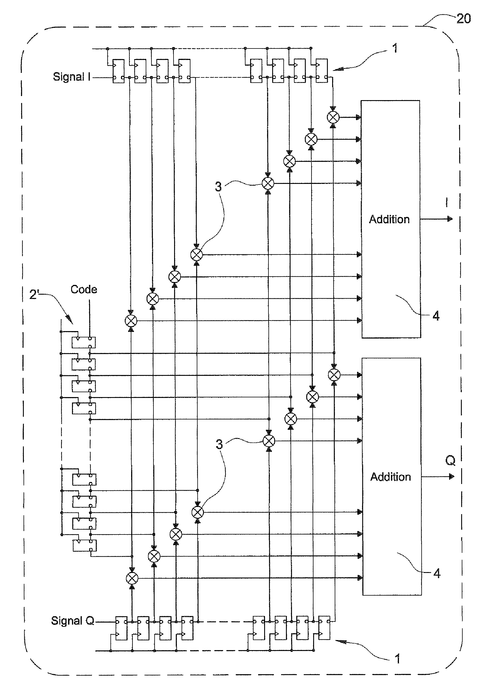
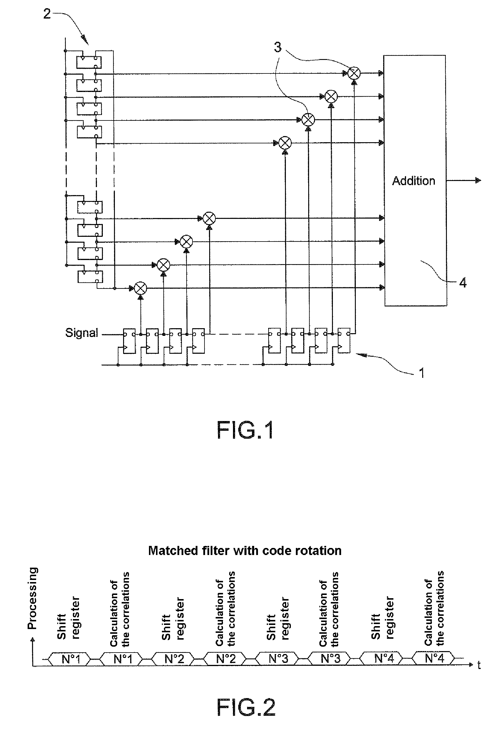
[0019]Hereinafter, the signal received converted into baseband and sampled at N kHz, N being the number of code chips considered over the period of the code, will be called the sampled signal. Here, N=2046=2×10²³. The operation of one of these sub-structures will be described in conjunction with FIG. 1.

[0020]The signal received, whose frequency is compensated so as to take the Doppler effect into account, is loaded into a nonrotating shift register 1 and the code is loaded into a rotating shift register 2. The length N of the shift register represents the number of code chips considered over the period of the code, i.e. 1 ms for example for GPS. To fully load the signal into its shift register 1, it is necessary to wait N clock cycles. This first step of register loading is represented on the timechart of FIG. 2, by the labelShift register”.

[0021]Then the signal remains fixed in its shift register 1 and the code performs N rotations around itself in the rotating shift register 2. ...


PUM


Abstract

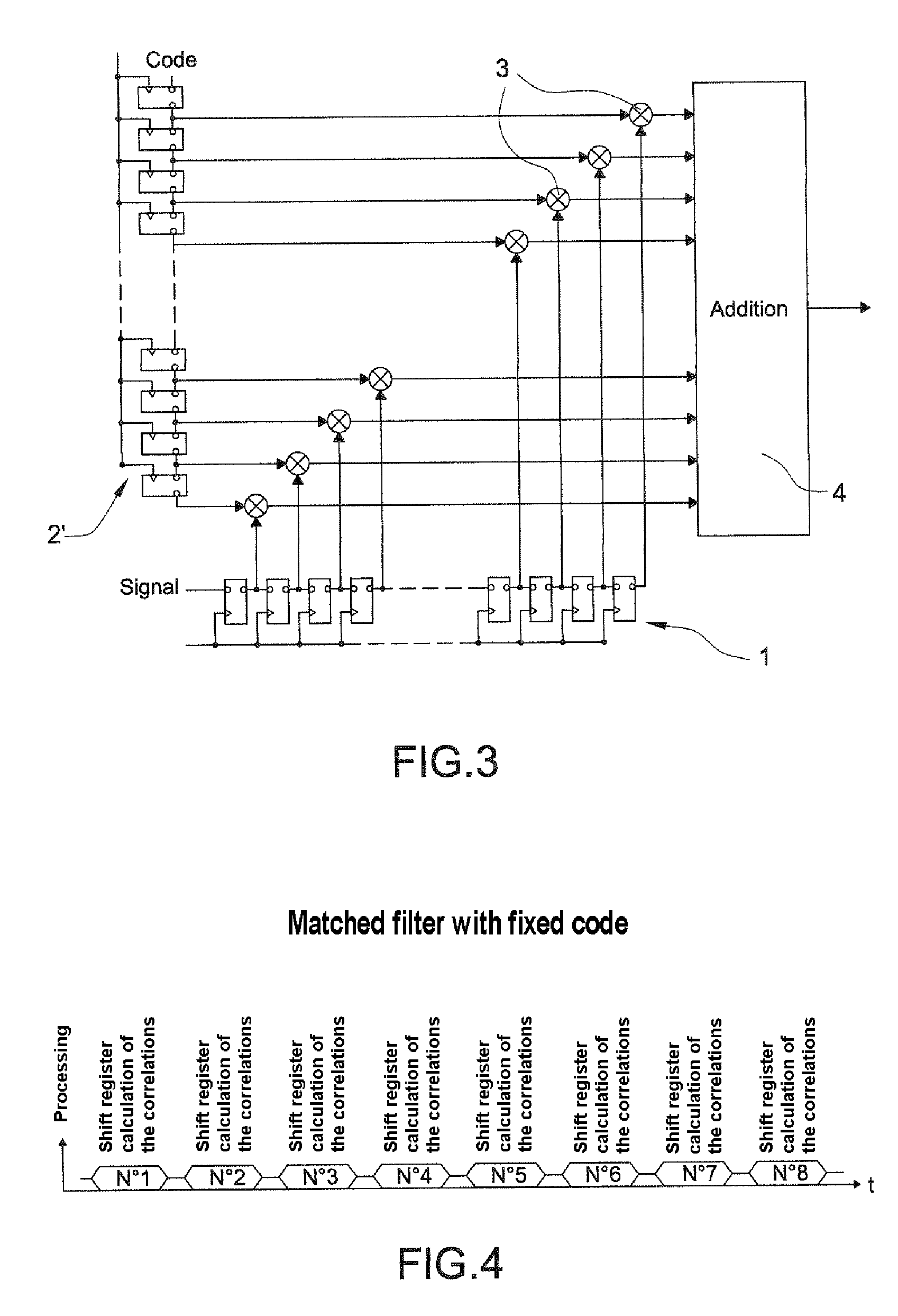
The invention relates to a method of receiving a radionavigation signal. Over a first determined time correlations of the sampled signal received are calculated with a locally generated code of period T. The signal is received and the code is shifted with respect to one another from one correlation to the next correlation. Over the determined time, the signal is shifted from one correlation to the next, the code being fixed.

Description

CROSS-REFERENCE TO RELATED APPLICATIONS[0001]The present Application is based on International Application No. PCT / EP2005 / 055169, filed on Oct. 11, 2005, which in turn corresponds to French Application No. 04 10953 filed on Oct. 15, 2004, and priority is hereby claimed under 35 USC §119 based on these applications. Each of these applications are hereby incorporated by reference in their entirety into the present application.BACKGROUND OF THE INVENTION[0002]The invention relates to the reception of a radionavigation signal originating from a satellite-based positioning system such as the GPS system (acronym of the expression “Global Positioning System”).[0003]To operate properly, contemporary receivers generally require direct line of sight satellite reception. Positioning rapidly deteriorates especially in terms of accuracy and acquisition time, when reception is disturbed as is the case inside a building or more generally in a degraded environment.[0004]The operation of the GPS sys...

Claims


Application Information

Patent Timeline
IPC IPC(8): H04B1/00H04K1/10H04L27/28
CPCG01S19/30
Inventor RAFFEGEAU, JEAN-PIERRE
Owner MITAC INT CORP
Learn More