Coil component

a coil and component technology, applied in the field of coil components, can solve the problems of inability to form solid-state coils, and the inability to obtain sufficient adhesion strength between them, and achieve the effects of increasing the adhesion strength of the coil component with respect to the mounting substrate, increasing the bonding area, and increasing the bonding strength between the terminal electrode and the flange par

Active Publication Date: 2020-01-02
MURATA MFG CO LTD
View PDF2 Cites 2 Cited by
  • Summary
  • Abstract
  • Description
  • Claims
  • Application Information

AI Technical Summary

Benefits of technology

[0020]According to the above-described coil component, each terminal electrode further includes the end surface electrode portion in addition to the bottom surface electrode portion, and the bottom surface electrode portion and the end surface electrode portion are covered in a continuous manner by at least the plating film. Therefore, the bonding area between each terminal electrodes and the respective flange part of the drum-shaped core is increased, and therefore the bonding strength between the terminal electrode and the flange part can be increased. Furthermore, when the coil component is mounted using solder, an adequate solder fillet is formed along the end surface electrode portion and the plating film formed thereon. Due to these two points, the adhesion strength of the coil component with respect to the mounting substrate when the coil component is in a mounted state can be increased.
[0021]Furthermore, since each terminal electrode has an end surface electrode portion independently of the bottom surface electrode portion, the adhesion strength of the coil component with respect to the mounting substrate can be increased in accordance with the height of the end surface electrode portion as described above even when the heights of adjacent surface extension portions of the bottom surface electrode portion are not large. Therefore, it is possible to both make adhesion strength in a mounted state high and make it unlikely that unwanted contact between wires on the winding core part and terminal electrodes on the flange parts will occur.

Problems solved by technology

In addition, when the height H1 of the adjacent surface extension portions is small, adequate solder fillets will not be formed when the common mode choke coil 1 is mounted on the mounting substrate, and it is unlikely that sufficient adhesion strength will be obtained between the common mode choke coil 1 mounted in this state and the mounting substrate.
This problem is not limited to a winding-type common mode choke coil and a similar problem may also arise in other winding-type coil components that include a plurality of wires and in which a plurality of terminal electrodes are provided on flange parts thereof such as a winding-type transformer or a balun.

Method used


Image

  • Coil component
  • Coil component
  • Coil component

Examples


Embodiment Construction

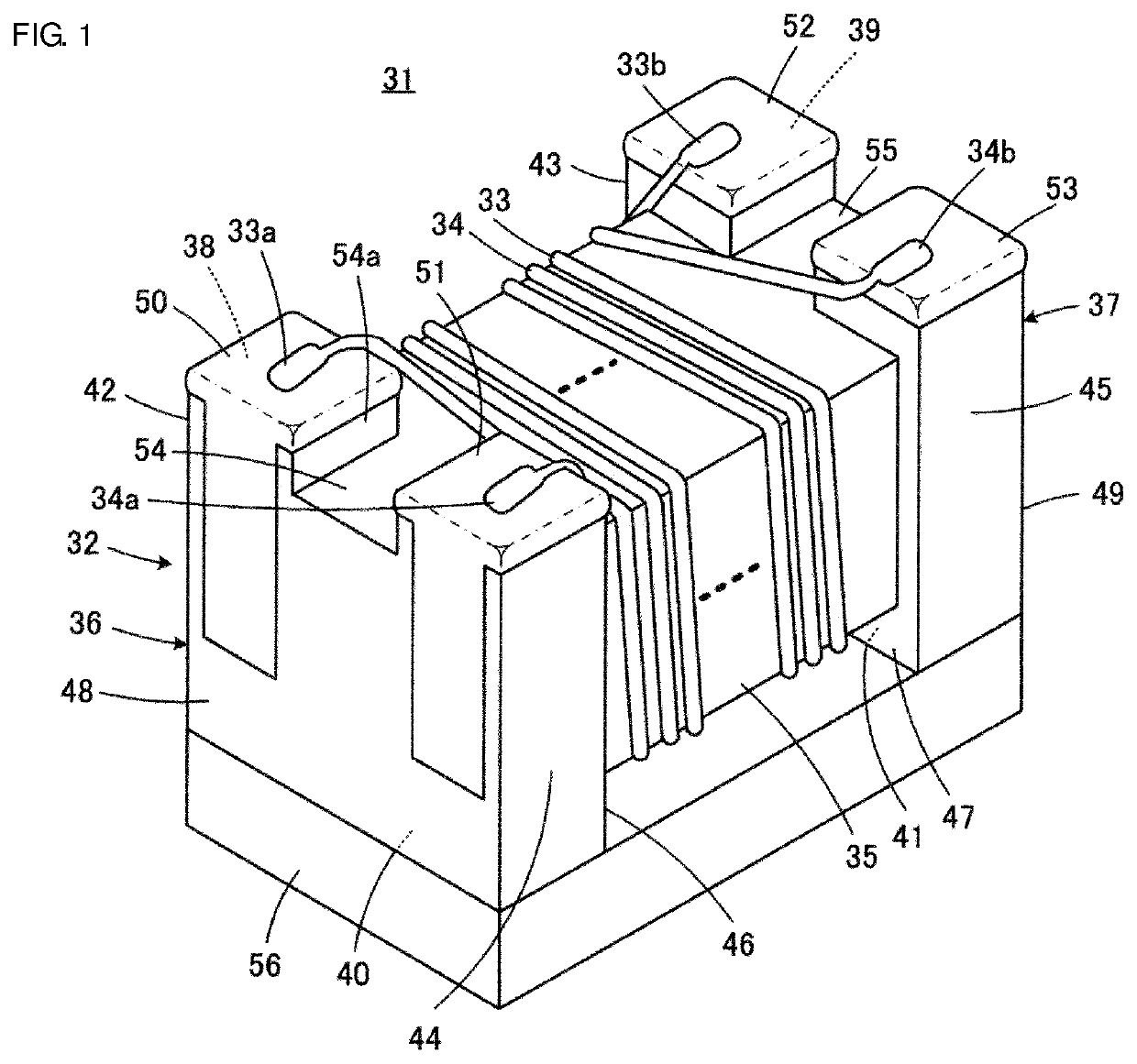
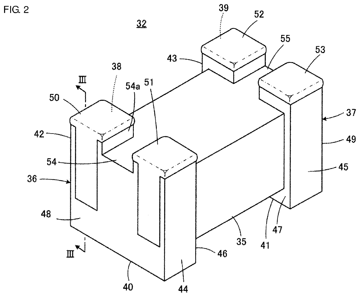
[0028]A coil component 31 according to an embodiment of the present disclosure will be described while referring to FIGS. 1 and 2. In FIGS. 1 and 2, the coil component 31 and a substantially drum-shaped core 32 are illustrated with the surface that will face a mounting substrate being on the upper side. The illustrated coil component 31 is included in a common mode choke coil, for example.

[0029]The drum-shaped core 32 of the coil component 31 includes a winding core part 35 that extends in an axial direction and around which a first wire 33 and a second wire 34 are arranged, and a first flange part 36 and a second flange part 37 that are respectively provided at a first end and a second end, which are opposite ends, of the winding core part 35. The drum-shaped core 32 may be formed of a non-conductive material, more specifically, a non-magnetic material such as alumina, a magnetic material such as ferrite, or a resin, and is preferably formed of a ceramic such as alumina or ferrite....


PUM

PropertyMeasurementUnit
thicknessaaaaaaaaaa
thicknessaaaaaaaaaa
thicknessaaaaaaaaaa

Abstract

A coil component in which a terminal electrode includes a bottom surface electrode portion that is positioned along a bottom surface of a flange part, an end surface electrode portion that is positioned along an outer end surface of the flange part, and a plating film that covers the bottom surface electrode portion and the end surface electrode portion in a continuous manner. The bottom surface electrode portion contains Ag and Si. The end surface electrode portion is composed of a metal film.

Description

CROSS-REFERENCE TO RELATED APPLICATION[0001]This application claims benefit of priority to Japanese Patent Application No. 2018-125898, filed Jul. 2, 2018, the entire content of which is incorporated herein by reference.BACKGROUNDTechnical Field[0002]The present disclosure relates to a coil component, and in particular relates to a winding-type coil component equipped with at least two wires.Background Art[0003]FIG. 5 is FIG. 1 from Japanese Unexamined Patent Application Publication No. 11-204346. FIG. 5 illustrates the appearance of a drum-shaped core 2 that is included in a winding-type common mode choke coil, as an example of a winding-type coil component. FIG. 5 illustrates the drum-shaped core 2 in an orientation where a surface thereof that will face a mounting substrate faces upward.[0004]The common mode choke coil includes the drum-shaped core 2, and a first wire and a second wire (not illustrated), which form inductors. The drum-shaped core 2 has a winding core part 5, and ...

Claims


Application Information

Patent Timeline
Patent Type & Authority Applications(United States)
IPC IPC(8): H01F27/29H01F27/28H01F27/24
CPCH01F27/29H01F27/2823H01F27/24H01F27/292H01F27/306H01F17/045H01F27/2828
Inventor TAKEZAWA, KAORIKOBAYASHI, KOHEI
Owner MURATA MFG CO LTD
Why Eureka
Try Eureka