Optical Coherence Metrology and Tomography with Improved Registration

a technology of optical coherence and tomography, applied in image analysis, medical science, diagnostics, etc., can solve the problems of complex equipment, high cost of mri, deformation and thinning of inner parts, etc., and achieve the effect of improving registration

Active Publication Date: 2019-12-05
CYLITE
View PDF0 Cites 18 Cited by
  • Summary
  • Abstract
  • Description
  • Claims
  • Application Information

AI Technical Summary

Benefits of technology

[0011]It is an object of the present invention to overcome or ameliorate at least one of the limitations of the prior art, or to provide a useful alternative. It is an object of the present invention in a preferred form to provide spectral domain OCT apparatus and methods with the ability to measure total eye shape. It is another object of the present invention in a preferred form to provide spectral domain OCT apparatus and methods for ocular metrology or tomography with improved registration.

Problems solved by technology

The condition can lead to deformation and thinning of the inner parts of the eye, increasing the incidence of retinal detachment, cataracts, glaucoma and blindness.
However MRI requires high cost, complex equipment and lacks the accuracy required to track small developmental changes over periods of weeks and months.
While spectral domain OCT has proved effective at providing measurements of various ocular layers and depths, for a number of reasons existing OCT techniques are not well suited for obtaining accurate information on total eye shape.
Among these reasons is a difficulty in measuring eye length, defined as the distance between the corneal apex and the fundus, in a single exposure.
A fundamental problem is that a broad source bandwidth, i.e. large Δλ, is required to provide the short coherence length necessary for depth resolution, but for a given detector array this limits the depth range over which the sample beam can interfere with the reference beam.
However due to the maximum exposure limits in a clinical setting, or limitations in the available optical power, it is not always possible to obtain measurements over time periods sufficiently short to preclude eye movement, i.e. less than a few milliseconds.
The '881 patent doesn't provide any guidance as to how a high signal to noise ratio measurement can be achieved when sampling over a large area of the eye, as it is not possible to compute from the limited acquired data set the lateral and axial position of the eye to co-register accurately the lateral and axial on-eye locations of the various enhanced axial scans which are described.
Consequently, several important optical properties of the eye cannot be calculated from the obtained set of axial scans.
Although a line scan system allows some capability for locating the position of the scan on the cornea in one axis it is not possible to ensure the position of the slice unambiguously for registration of a series of slices to build a more complete correctly registered image of the optical interfaces in the eye.
Additionally the slit aperture is able to provide a high-resolution axial scan but does not provide a means to remove crosstalk from different lateral positions.
In particular, in regions where high intensity specular reflection transitions to low intensity scattering as occurs on the human cornea, it is difficult to prevent lateral crosstalk from high intensity regions overwhelming and corrupting the results from neighbouring points at different depths.
The ability of OCT to measure total eye shape is also compromised by the eye's focusing power.
To form a small beamlet at the retina it is necessary to illuminate the cornea with a collimated beam, which lacks the precision to map the front surface of the eye.
Furthermore an array of parallel beamlets used to measure anterior portions of the eye will be focused onto one region of the retina, and therefore can't provide a topographic map of the back of the eye.
An additional difficulty for using OCT to measure eye shape is that the apparent curvature of the retina is influenced by the position of the OCT instrument relative to the eye.

Method used


Image

  • Optical Coherence Metrology and Tomography with Improved Registration
  • Optical Coherence Metrology and Tomography with Improved Registration
  • Optical Coherence Metrology and Tomography with Improved Registration

Examples


first embodiment

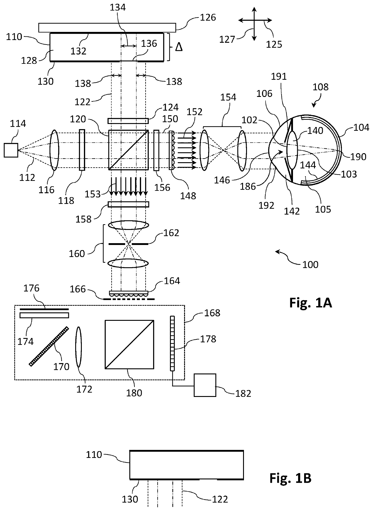
[0091]A first aspect of the present invention concerns spectral domain OCT apparatus and methods with increased depth of field, in particular having sufficient depth of field for single shot measurement of eye structures and parameters including eye length. FIG. 1A shows in schematic form a spectral domain OCT apparatus 100 according to the invention, suitable for ocular metrology or tomography with registration of intra-ocular structures, such as the anterior or posterior lens surfaces 102, 103 or the choroid 104, to the anterior sclera 106 of a sample eye 108. Light 112 from a broadband optical source 114 such as a superluminescent diode with centre wavelength 840 nm and bandwidth of 40 nm is collimated by a collimating element 116 such as a lens or a parabolic mirror, linearly polarised by a polariser 118 and then split by a polarisation beam splitting cube (PBS) 120 into reference and sample beams 122, 150. In preferred embodiments the reference arm includes a multi-length delay...

third embodiment

[0124]FIG. 5A shows in schematic form a modification of the sample arm optics of the apparatus 100 shown in FIG. 1A, to provide a spectral domain OCT apparatus according to the invention. This modification, which can also be applied to the sample arm optics shown in FIG. 4, introduces improved aperturing at the front end of the sample arm to provide better isolation of the returning sample beamlets. As will be explained, this improved aperturing suppresses crosstalk between returning sample beamlets, in particular by suppressing the passage of off-axis high intensity specular reflections. A wavefront 500 in the sample arm is directed towards a spatial sampling element in the form of a 2-D lenslet array 148 that forms a number of beamlets with waists 502 passing through a structured aperturing partition 504 with an aperture dimension comparable to the beam waist or first Rayleigh ring. The beamlets are then relayed by a second 2D lenslet array 506 to provide effective beam waists 508...


PUM


Abstract

Methods and apparatus are provided for optical coherence metrology or tomography across an extended area of an eye with improved registration. At least two optical coherence tomograms are acquired, with each tomogram containing data from regions of an anterior surface of the eye that are at least partially overlapping, and data from one or more deeper structures such as the retina or the anterior or posterior lens surfaces. The tomograms are then processed to register the data from the overlapping portions of the anterior surface regions, thereby registering the data from the deeper structures. In certain embodiments the reference arm of the apparatus comprises a compound reflector having at least two axially separated reflective surfaces for applying differential delays to different portions of the reference beam. The depth of field of the apparatus is thereby extended to enable measurement of eye length. In certain embodiments eye length measurements at a number of angles of incidence provide information on total eye shape.

Description

FIELD OF THE INVENTION[0001]The invention relates to apparatus and methods for ocular metrology, in particular for measuring the shape of the human eye using optical coherence tomography (OCT) techniques. However it will be appreciated that the invention is not limited to this particular field of use.RELATED APPLICATIONS[0002]The present application claims priority from Australian Provisional Patent Application No 2017900245 entitled ‘Optical Coherence Metrology and Tomography with Improved Registration’ filed on 28 Jan. 2017, the contents of which are incorporated herein by reference.BACKGROUND OF THE INVENTION[0003]Any discussion of the prior art throughout the specification should in no way be considered as an admission that such prior art is widely known or forms part of the common general knowledge in the field.[0004]Measurement of many if not all of the optical surfaces in the human eye, as well as total eye shape, provides important information about the progression of variou...

Claims


Application Information

Patent Timeline
Patent Type & Authority Applications(United States)
IPC IPC(8): A61B3/10G06T7/33
CPCA61B3/102G06T7/33G06T2207/10101G06T2207/30041
Inventor FRISKEN, STEVEN JAMESFRISKEN, GRANT ANDREW
Owner CYLITE
Why Eureka
Try Eureka