
Heat pump for automobile

a technology for heat pumps and automobiles, applied in heat pumps, lighting and heating apparatus, compression machines with several condensers, etc., can solve the problems of reducing the travel distance of the vehicle, requiring defrosting, and reducing the heating efficiency of the source during the heating operation or the cooling operation. , to achieve the effect of improving heating performance, and reducing the heating efficiency

Active Publication Date: 2019-11-21
ERAE AUTOMOTIVE SYST
View PDF0 Cites 8 Cited by
  • Summary
  • Abstract
  • Description
  • Claims
  • Application Information

AI Technical Summary

Benefits of technology

The present invention provides a heating system that can efficiently defrost without reducing heating efficiency compared to the related art. It compensates for insufficient heating using waste heat from electronic components or a cabin room. It also prevents high-temperature, high-pressure refrigerant from passing through the inner heat exchanger during cooling operation, resulting in improved prevention of heat pick-up. A separate dehumidification line is provided for maximizing dehumidifying-heating operation.

Problems solved by technology

However, in the case of the electric vehicles, neither an engine nor a coolant is provided as a heat source, and thus there is no choice but to depend on a battery.
There is a technical difficulty in that a traveling distance of the vehicle is remarkably reduced when heating is performed using the battery.
Therefore, if air conditioners mounted in vehicles using a general engine are applied to the electric vehicles and the hybrid vehicles with no change, there occurs a problem that a heat source during a heating operation or a driving force of a compressor during a cooling operation is not sufficiently provided.
Meanwhile, if open air has a temperature too low during a heating operation of a heat pump vehicle, a phenomenon in which frost is formed on an outer heat exchanger occurs, and thus a defrosting operation is required.
However, this switching of the circulating direction of the refrigerant is responsible for reducing heating performance of an inner heat exchanger, and leads to a result of failing to provide heating during a defrosting operation if necessary.
However, an effective method for solving a problem with a drop in heating performance during the defrosting operation of the heat pump is insufficient so far.
It is well known that remodeling of the conventional air conditioner or development of a new concept air conditioner is required since there is a limit to the battery for the vehicle.
Due to the formed frost, heat exchange is not efficient at the outer heat exchanger, which leads to a problem that the heating performance is dropped.

Method used


Image

  • Heat pump for automobile
  • Heat pump for automobile
  • Heat pump for automobile

Examples


Embodiment Construction

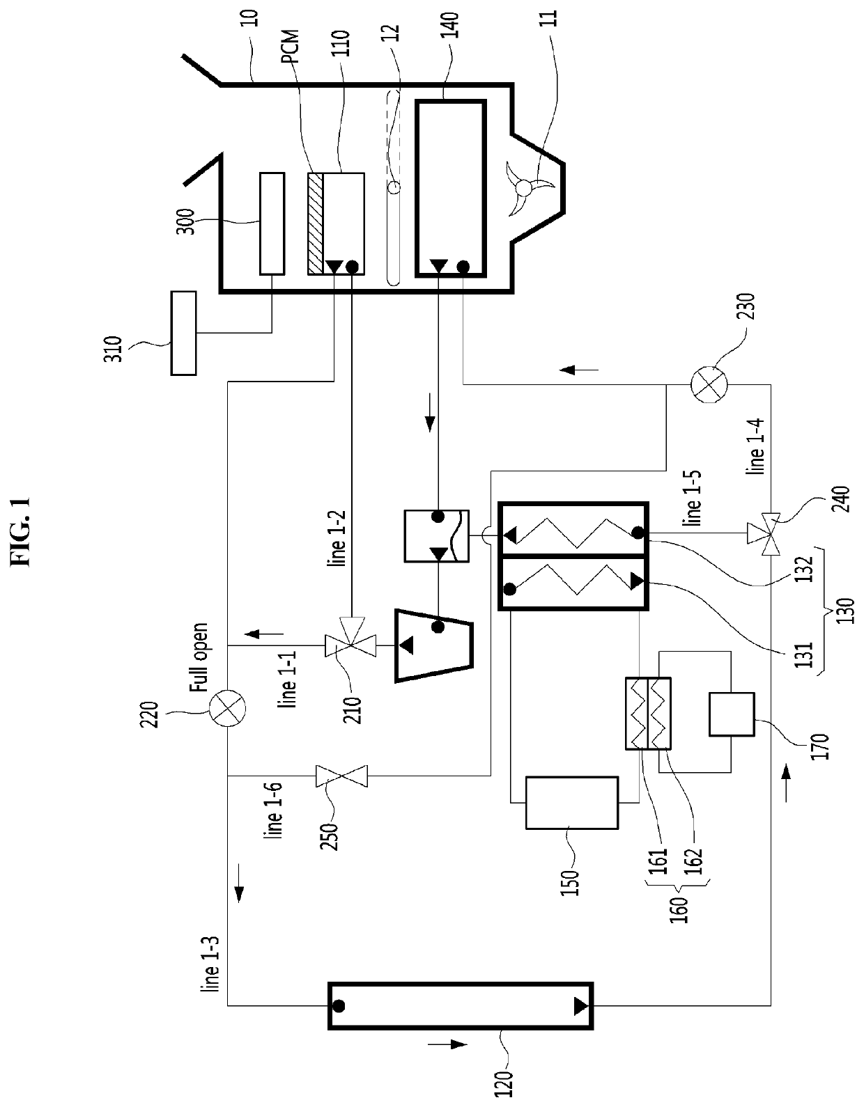
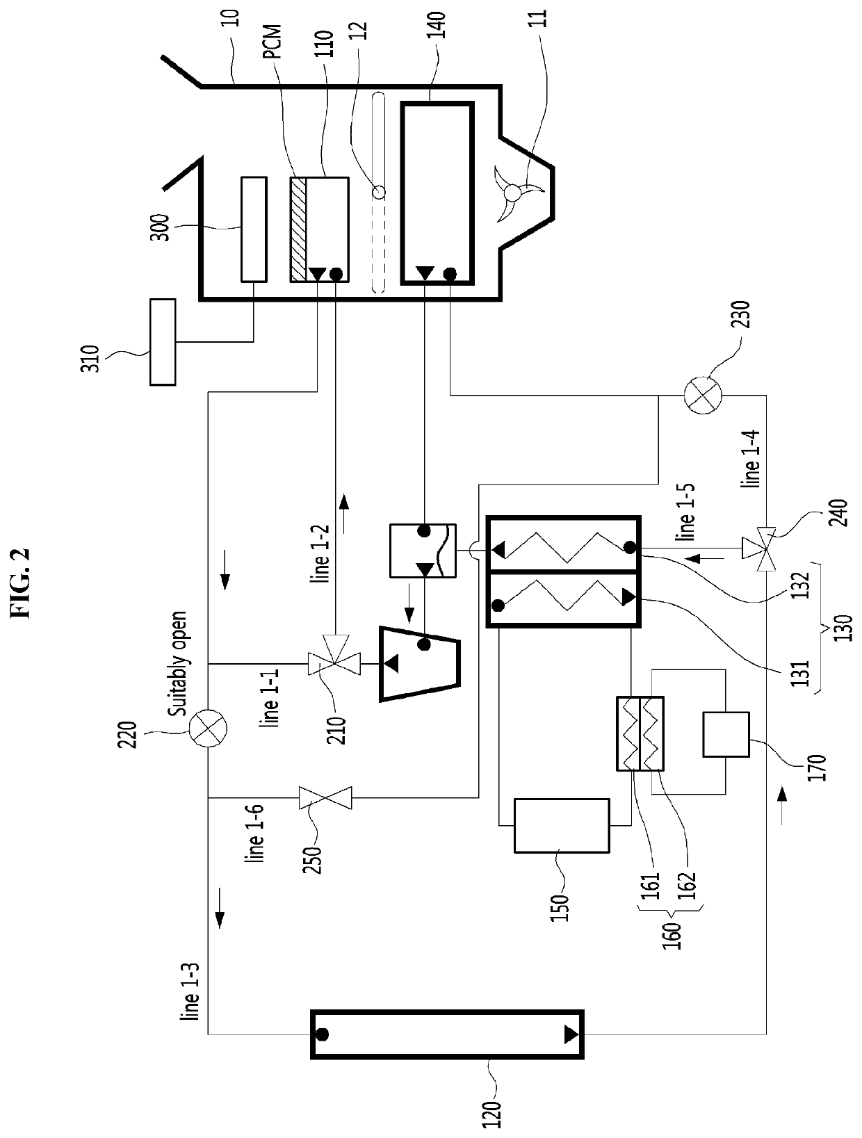
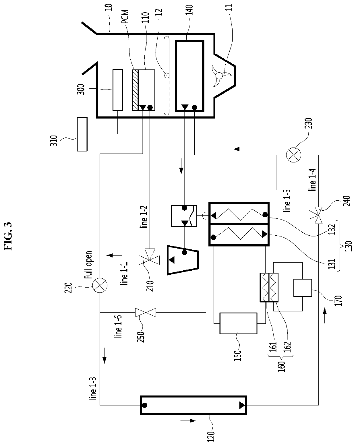
[0040]According to an embodiment of the present invention, a heat pump for a vehicle includes: a compressor configured to compress and discharge a refrigerant; an inner heat exchanger configured to allow a heat exchange between the refrigerant and air in an interior of the vehicle; an outer heat exchanger configured to allow a heat exchange between the refrigerant and open air; a first directional control valve configured to supply the refrigerant discharged from the compressor either to the inner heat exchanger or toward the outer heat exchanger without going through the inner heat exchanger according to air conditioning modes of the vehicle; a first expansion means disposed on a refrigerant line between the inner heat exchanger and the outer heat exchanger and provided to allow expansion of the refrigerant; a second expansion means disposed on the refrigerant line and provided to allow expansion of the refrigerant that has passed through the outer heat exchanger; an evaporator pro...


PUM


Abstract

A heat pump for a vehicle is provided in which the heat pump includes a compressor, an inner heat exchanger, an outer heat exchanger, a first expansion unit, a second expansion unit, an evaporator, an accumulator, a third heat exchanger, a first directional control valve, a second directional control valve, and a dehumidification line, and performs cooling, heating, defrosting, and dehumidifying operations according to the flow of a refrigerant.

Description

BACKGROUND1. Technical Field[0001]The present invention relates generally to a heat pump for a vehicle and, more particularly, to a heat pump for a vehicle which includes a first directional control valve, a second directional control valve, a dehumidification line, and so on and performs cooling / heating / defrosting / dehumidifying operations according to the flow of a refrigerant.2. Description of Related Art[0002]In recent years, a desire to introduce vehicles using alternative energy as a power source or low emission vehicles in association with global environment issues and a request to improve an atmospheric environment has been rising.[0003]Thus, electric vehicles using a battery and an electric motor and hybrid vehicles using an electric motor in combination with an engine as a driving source have attracted attention as vehicles using alternative energy.[0004]In the case of general internal combustion engines using light oil or heavy oil as fuel, a heating operation can be perfo...

Claims


Application Information

Patent Timeline
Patent Type & Authority Applications(United States)
IPC IPC(8): B60H1/00F25B27/02F25B30/06F25B47/02F25B49/02B60H1/14
CPCF25B47/022F25B30/06B60H2001/00949B60H1/00492F25B49/02F25B27/02B60H1/00385B60H1/143B60H1/00885B60H1/00899B60H1/00921B60H2001/00928B60H2001/00961B60H1/039B60H1/32281F25B25/005F25B5/04F25B6/04F25B2600/2507F25B2700/11F25B41/20B60H1/3207
Inventor KIM, JONG WONJANG, HO YOUNGCHOI, JUN HO
Owner ERAE AUTOMOTIVE SYST
Learn More