Stator vane for a turbine of a turbomachine

a turbomachine and turbine technology, applied in the direction of engines, machine/engines, leakage prevention, etc., can solve the problems of mechanical problems, tip clearance flow, flow loss, etc., and achieve the effect of reducing the cooling air requirement in the casing, reducing the efficiency loss, and reducing the temperatur

Active Publication Date: 2019-10-31
MTU AERO ENGINES GMBH
View PDF0 Cites 3 Cited by
  • Summary
  • Abstract
  • Description
  • Claims
  • Application Information

AI Technical Summary

Benefits of technology

[0024]In general, the flow through the stator vane airfoil channel; i.e., suctioning at a radially inner position and blowing out at a radially outer position, is caused by a pressure difference across the stator vane. The velocity can be set via the size (the cross-sectional area) of the outlet; the orientation determines the direction of the exiting fluid flow. This opens up the described design options to the effect that flow losses in the annular space, and thus efficiency losses, can be reduced. Friction losses, and thus local heating, e.g., of the outer shroud, can also be minimized.
[0025]Preferably, the turbine module has a plurality of stages, each having a stator vane ring and a downstream rotor blade ring. Preferably, the stator vanes in all stages of the turbine are then provided with corresponding stator vane airfoil channels, so that an overall lower temperature is attained in the casing region. The cooling air requirement in the casing decreases and, in addition, the gap stability may be improved.

Problems solved by technology

In addition, tip clearances also cause flow losses (tip clearance flow).
In a prior art design, hot working gas flows around the outer shroud of the rotor blade disposed downstream of the stator vane, whereby the outer shroud is strongly heated, which can cause mechanical problems.
The high centrifugal loads in combination with high temperatures lead to high creep strains.
This is because the inflowing sealing fluid has a significantly different velocity and direction than the working gas conveyed in the annular space and if not suctioned off would significantly disturb the mainstream flow.

Method used


Image

  • Stator vane for a turbine of a turbomachine
  • Stator vane for a turbine of a turbomachine
  • Stator vane for a turbine of a turbomachine

Examples


Embodiment Construction

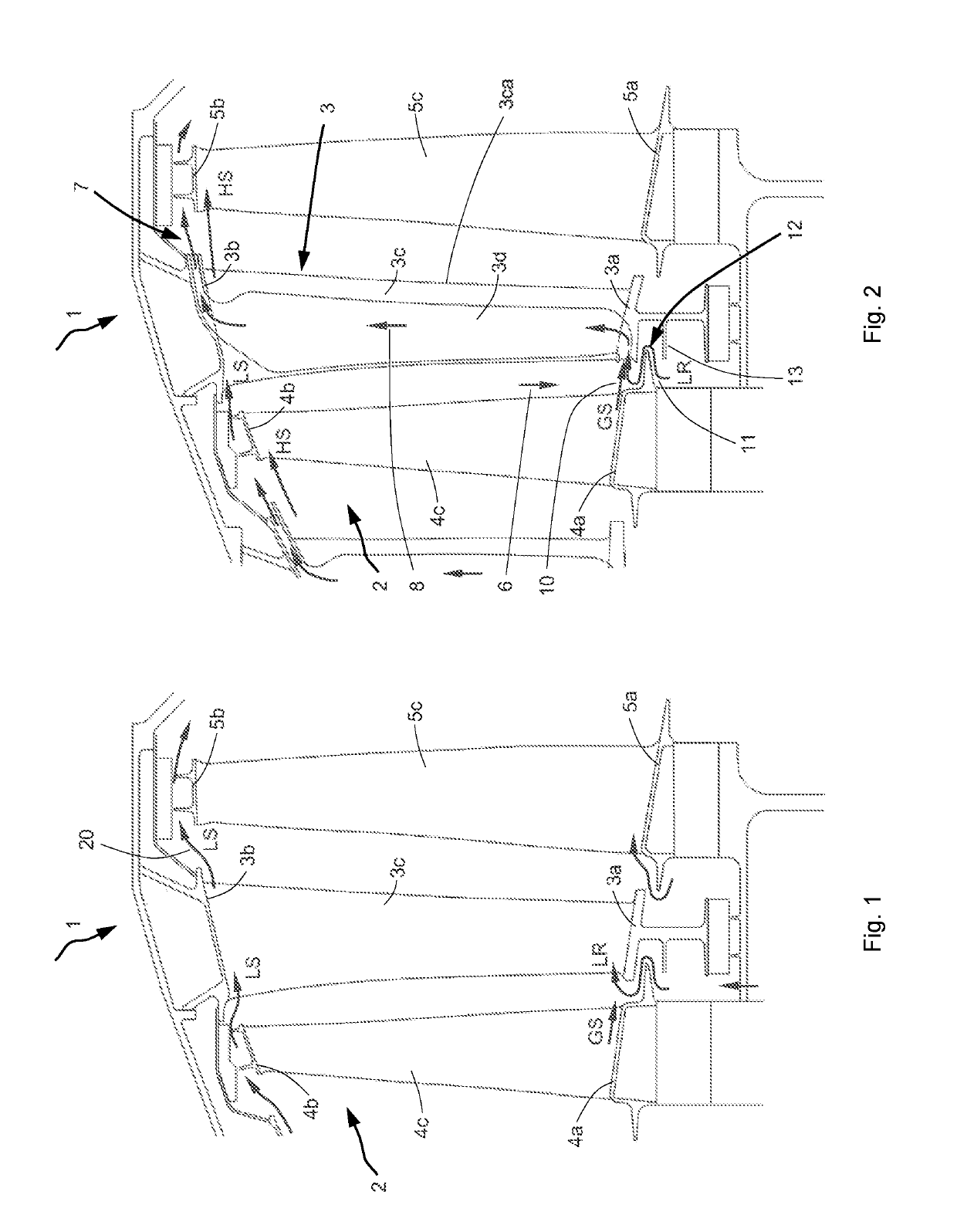
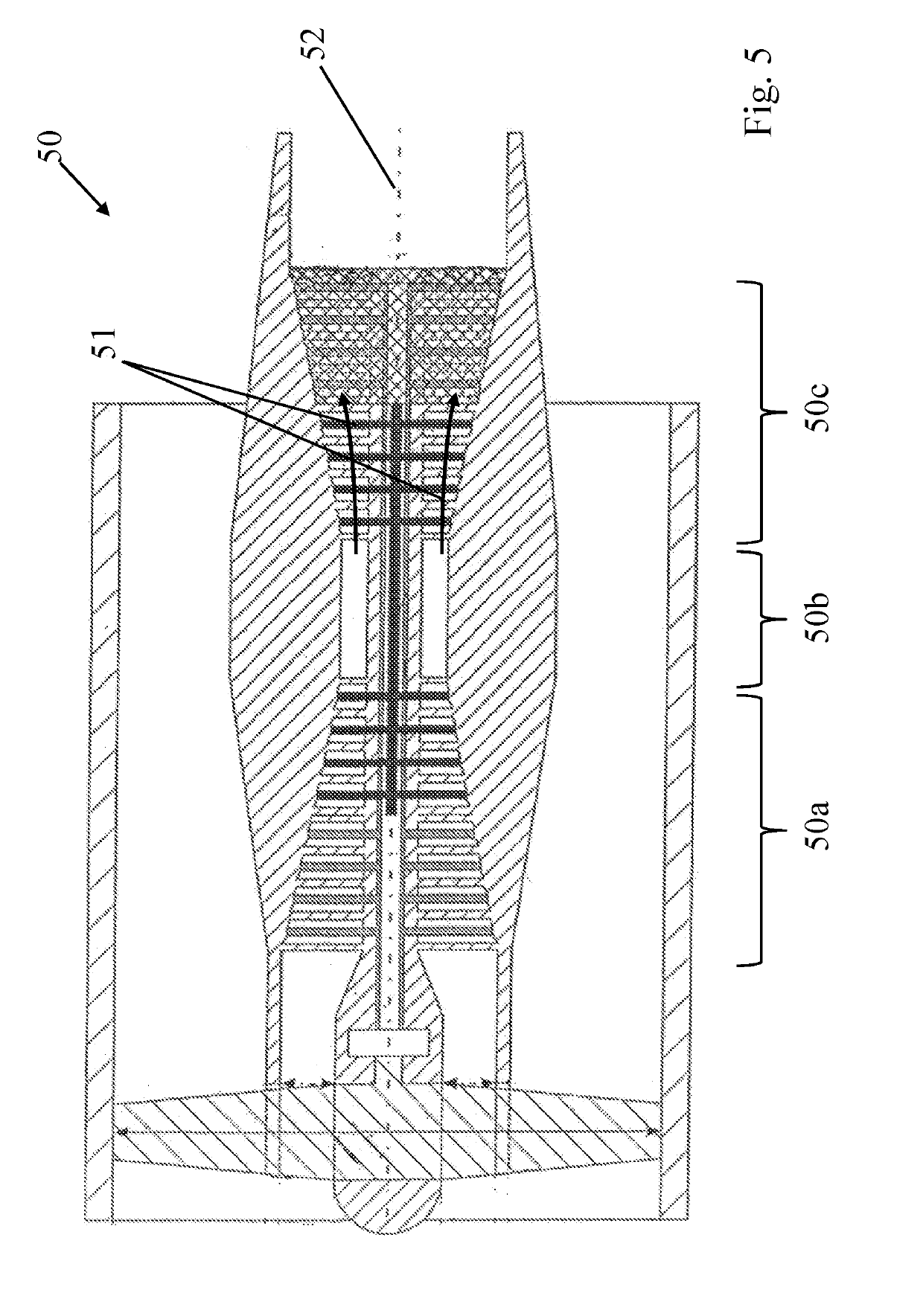
[0037]FIG. 2 shows, in axial cross-sectional view, a portion of a turbine module 1. During operation, working gas traveling from the combustor (located to the left of turbine module 1) to the nozzle (located to the right thereof) flows through an annular space 2 formed by turbine module 1 (see also FIG. 5 for illustration). Disposed in this annular space 2 is a stator vane 3 having an inner shroud 3a, an outer shroud 3b, and a stator vane airfoil 3c therebetween. A rotor blade 4 is disposed upstream of stator vane 3; a rotor blade 5 is disposed downstream thereof. Stator vane 3 is shown in cross-section. A stator vane airfoil channel 3d extends from radially inward to radially outward through stator vane airfoil 3c. The inlet 6 into stator vane airfoil channel 3d is located at inner shroud 3a of stator vane 3, and specifically at the upstream leading edge thereof. The outlet 7 of stator vane airfoil channel 3d is disposed radially outwardly of the outer shroud 3b and is axially offs...


PUM


Abstract

A stator vane (3) for a turbine (50c) of a turbomachine (50), the stator vane having a stator vane airfoil (3c), an inner shroud (3a) and an outer shroud (3b), the inner shroud (3a) and the outer shroud (3b) bounding an annular space (2), in which working gas (51) is conveyed during operation, radially with respect to a longitudinal axis (52) of the turbomachine (50), and the stator vane airfoil (3c) having a stator vane airfoil channel (3d) extending through its interior between a radially inner inlet (6) and a radially outer outlet (7). A characteristic features is that the inlet (6) is disposed in such a manner that a gas (8) flowing through the stator vane airfoil channel (3d) during operation is at least partially formed of the working gas (51) conveyed in the annular space (2), and thus the working gas is redistributed from radially inward to radially outward.

Description

[0001]This claims the benefit of German Patent Application DE102018206259.5, filed Apr. 24, 2018 and hereby incorporated by reference herein.[0002]The present invention relates to a stator vane for a turbine of an axial turbomachine.BACKGROUND[0003]The turbomachine may be, for example, a jet engine, such as a turbofan engine. The turbomachine is functionally divided into a compressor, a combustor and a turbine. In the case of the jet engine, for example, intake air is compressed by the compressor and mixed and burned with jet fuel in the downstream combustor. The resulting hot gas, a mixture of combustion gas and air, flows through the downstream turbine and is expanded therein. The hot gas, also referred to as working gas, flows through a volume on a path from the combustor via the turbine to the nozzle. The present discussion initially considers a stator vane or a turbine module, and thus a portion of this path or volume that will hereinafter be referred to as “annular space.”[000...

Claims


Application Information

Patent Timeline
Patent Type & Authority Applications(United States)
IPC IPC(8): F01D25/12F01D9/04
CPCF01D25/12F05D2240/125F05D2260/201F01D9/041F01D9/065F01D11/001F01D11/06F01D11/10
Inventor KLINGELS, HERMANN
Owner MTU AERO ENGINES GMBH
Why Eureka
Try Eureka