
Transmitter circuit, communication unit and method for amplifying a complex quadrature signal

a transmission circuit and quadrature technology, applied in the field of transmission circuits, communication units, and amplifying complex quadrature signals, can solve the problems of reducing the efficiency loss that is suffered in normal operation of a conventional quadrature digital pa, and achieve the effect of increasing efficiency and increasing output power

Active Publication Date: 2016-05-05
XUESHAN TECH INC
View PDF4 Cites 8 Cited by
  • Summary
  • Abstract
  • Description
  • Claims
  • Application Information

AI Technical Summary

Benefits of technology

The patent describes a transmitter architecture that uses a digital Pa and a digital quadrature modulator to increase efficiency. The modulator remaps the data points to bring the "Q" value close to a limit, reducing the need for many cells in the "Q" dental power amplifier and minimizing phase change. The architecture can be hybrid between a polar and IQ transmitter, with the "Q" dental amplifier turned on with minimal current consumption to achieve a fine phase change. The efficiency loss associated with the "D" transmitter is alleviated by manipulating the "Q" data to a lower value within a limit, reducing the loss of efficiency. The use of a coarse phase change operation outside the "D" amplifier and a multiplexer or a PLL with a predefined limit or a fixed phase rotation can further improve efficiency. Overall, the architecture results in a more efficient transmitter.

Problems solved by technology

As a consequence, the loss of efficiency that is suffered in normal operation of a conventional quadrature digital PA may be reduced.

Method used


Image

  • Transmitter circuit, communication unit and method for amplifying a complex quadrature signal
  • Transmitter circuit, communication unit and method for amplifying a complex quadrature signal
  • Transmitter circuit, communication unit and method for amplifying a complex quadrature signal

Examples


Embodiment Construction

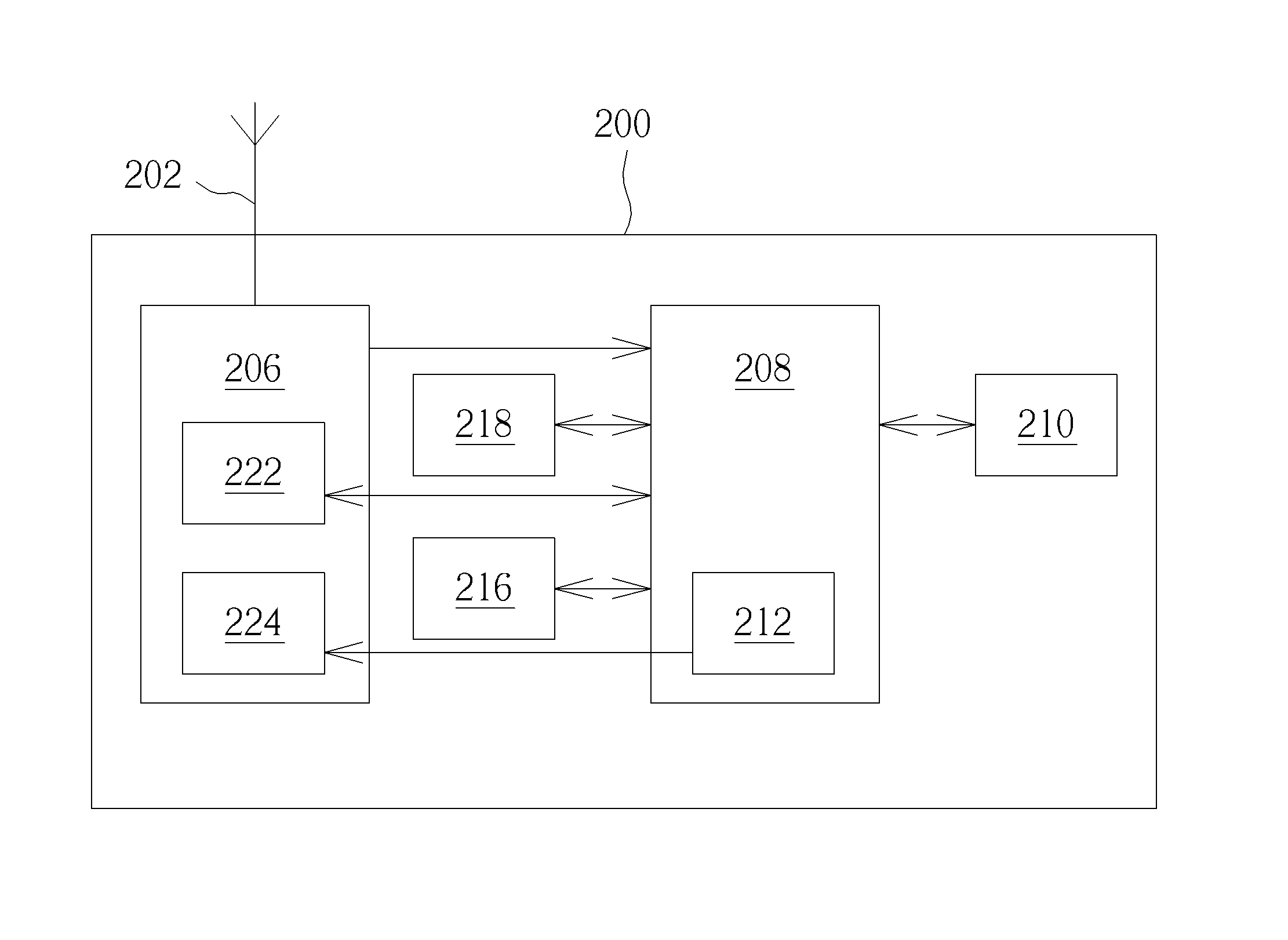
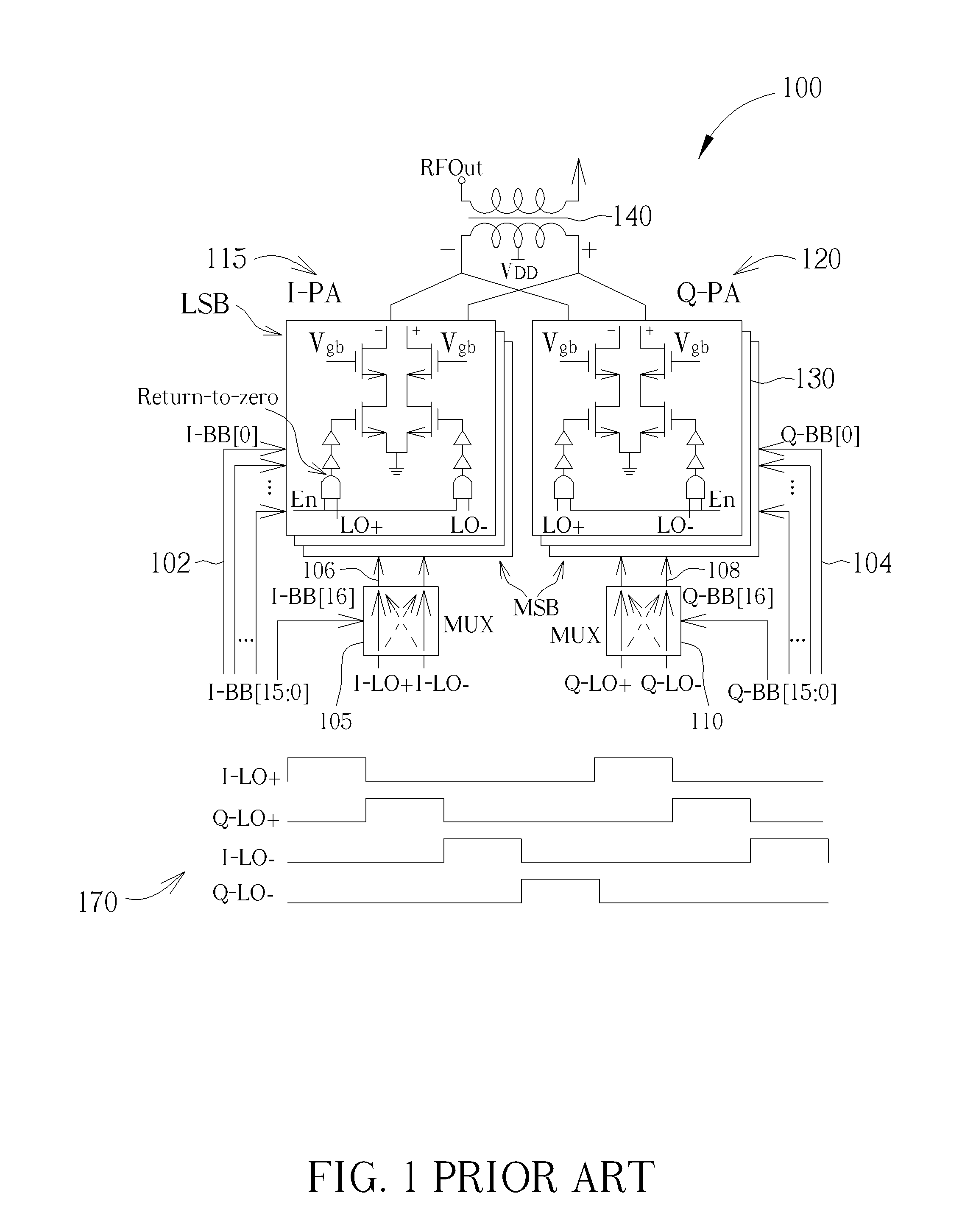
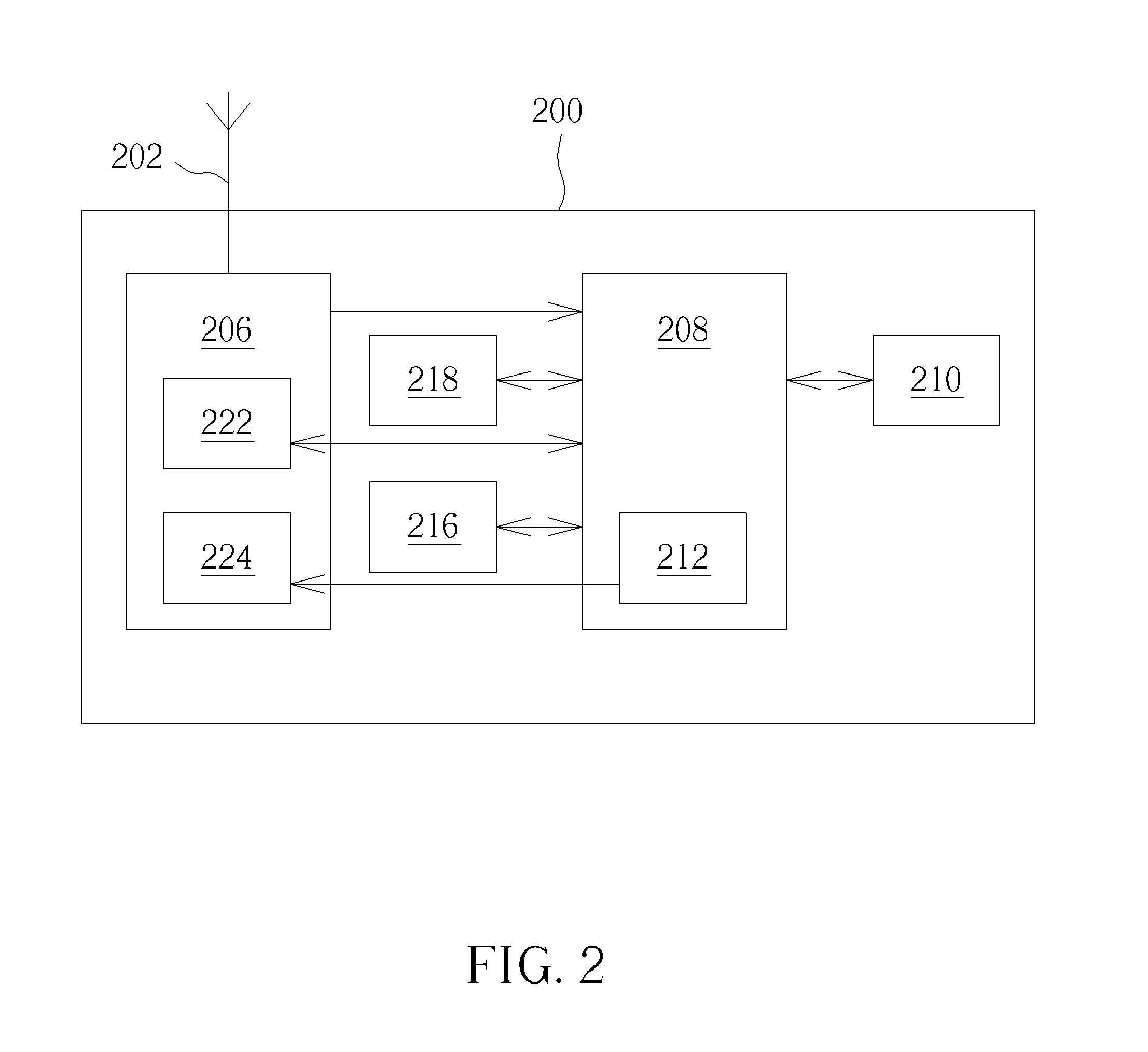
[0045]Examples of the invention will now be described with reference to a digital transmitter architecture and method. The digital transmitter circuit comprises a digital quadrature modulator configured to receive data to be transmitted and quadrature modulate the received data to at least a first, Q, modulated value and a second, I, modulated value; examine the quadrature modulated data to determine if the first, Q, modulated value exceeds a limit, and in response thereto selectively modify the quadrature modulated values to a first modified, Q′, modulated value and a second modified, I′, modulated value thereby bringing only a value of the first modified, Q′, modulated value to within the limit and a digital power amplifier, DPA, configured to amplify the digitally modulated data. In particular examples, a digital quadrature (de-)rotation of a constellation axis, thus yielding an opposite (de-)rotation of data located in the constellation may be used to modify the quadrature value...


PUM


Abstract

A transmitter circuit includes a frequency generation circuit configured to generate a local oscillator signal and a digital modulator configured to: receive data to be transmitted; quadrature modulate the received data to at least a first, Q, modulated value and a second, I, modulated value; examine the quadrature modulated data to determine if the first, Q, modulated value exceeds a limit, and in response thereto selectively modify the quadrature modulated values to a first modified, Q′, modulated value and a second modified, I′, modulated value thereby bringing only a value of the first modified, Q′, modulated value to within the limit. A local oscillator phase is selected in order to map the first modified, Q′, modulated value and second modified, I′, modulated value to desired quadrature values. A digital power amplifier, DPA, coupled to the digital quadrature modulator, is configured to amplify the quadrature modified modulated data.

Description

CROSS REFERENCE TO RELATED APPLICATIONS[0001]This application claims the benefit of U.S. provisional application No. 62 / 069,852, filed on Oct. 29, 2014 and incorporated herein by reference.BACKGROUND[0002]1. Field of the Invention[0003]The field of this invention relates to a transmitter circuit, a communication unit, and a method for amplifying a complex quadrature signal, and in particular a mechanism for amplifying a complex quadrature signal using a digital power amplifier.[0004]2. Background of the Invention[0005]In telecommunications, there has been a recent trend for device manufacturers to design wireless communication units that are capable of operating over multiple frequency bands, to enable the same device to operate in different geographical regions, as well as being able to switch between different service providers and different communication technologies. Hence, in the field of wireless (e.g., Radio Frequency (RF)) communication units, architectures for supporting co...

Claims


Application Information

Patent Timeline
IPC IPC(8): H04L27/26H04B1/04
CPCH04L27/2623H04B2001/0491H04B2001/0408H04B1/0475H04L27/365H03F3/24
Inventor MUHAMMAD, KHURRAMHUNG, CHIH-MING
Owner XUESHAN TECH INC
Learn More