Monitoring sensor for metered amounts of powder

Active Publication Date: 2019-07-18
HARRO HOFLIGER VERPACKUNGSMASCHEN
View PDF2 Cites 0 Cited by
  • Summary
  • Abstract
  • Description
  • Claims
  • Application Information

AI Technical Summary

Benefits of technology

The invention is a monitoring sensor with improved interchangeability of the sensor socket. The sensor socket is attached to a holding plate, which forms a jointly interchangeable unit with the sensor base body. The sensor base body has a bearing face or contact surface for the holding plate, while the monitoring sensor includes a holding magnet for pressing the holding plate against the contact surface. The sensor socket is positionally fixed in the sensor base body, ensuring accurate measurements. The sensor socket can be easily removed or inserted without the need for clamps or major effort. The sensor base body has a through opening that holds the sensor socket in place, ensuring accurate positioning and fixation in all lateral and rotational degrees of freedom. The holding plate produces an electrical grounding of the sensor socket, improving reproducibility of the measurement results. The monitoring sensor can also have a blast nozzle for cleaning the sensor socket of powder residues, ensuring constant dielectric parameters and avoiding measurement errors.

Problems solved by technology

But since powders in different batches with different formats are processed on the same dosing device, the need for the geometrical adaptation also leads to different sensor sockets having to be used.
During every format change, the adapting work on the monitoring sensor is limited to removing the existing sensor socket and replacing it with a sensor socket adapted to the format which is going to be processed.
Herein various difficulties occur in practice.
Due to vibrations or other actions of force, however, an axial shifting of the sensor sockets cannot be ruled out.
The mentioned unwanted relative movements may have a negative impact on the quality of the measurement signal and in the extreme case may even result in damage to the sensor.
Attempts to attach them with O-rings have resulted in a tendency to damage when the sockets are changed.
On the whole, the pulling out and the installing of the sensor sockets requires effort, which makes it difficult to retrofit the monitoring sensors installed in the machine, given the correspondingly cramped space conditions.

Method used


Image

  • Monitoring sensor for metered amounts of powder

Examples


Embodiment Construction

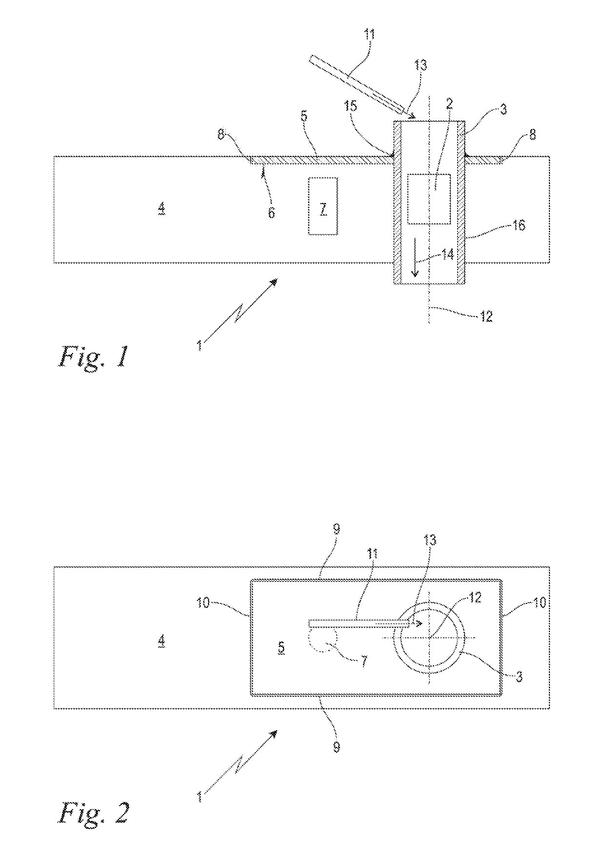
[0015]FIG. 1 shows in a schematic longitudinal section representation a monitoring sensor 1 configured according to an embodiment of the invention for the mass determination of metered amounts of powder 2 only indicated schematically here. The metered amounts of powder 2 shown here are pharmaceutical powder plugs compacted into so-called pellets, which plugs have been previously metered and measured in a sliding dispenser in a previously known manner, and therefore not described here. The term amounts of powder 2 chosen here, however, includes in the scope of the disclosure loose, amorphous amounts of powder and also amounts of powder compressed into quasi-solids, such as pellets, tablets, or the like, especially from the pharmaceutical industry, but also from other industries such as for example from the food supplement industry. The metering may also occur in a roller dispenser, in a disk dispenser, via a pipette or the like, in a previously known manner. The monitoring sensor 1 i...


PUM


Abstract

A monitoring sensor for metered amounts of powder includes a sensor socket to channel the metered amount of powder through it and a sensor base body, in which the sensor socket is held interchangeably. A holding plate is attached to the interchangeable sensor socket. The sensor base body has a contact surface for the holding plate. The monitoring sensor includes a holding magnet for pressing the holding plate against the contact surface.

Description

CROSS REFERENCE TO RELATED APPLICATION[0001]This application claims priority of European patent application no. 18152376.2, filed Jan. 18, 2018, the entire content of which is incorporated herein by reference.BACKGROUND OF THE INVENTION[0002]Especially in the pharmaceutical industry, powder-like formulations are employed, wherein suitable partial amounts from a powder stockpile need to be precisely measured or metered for the respective application. This occurs, for example, by means of roller or disk dispensers, which have metering bores with a calibrated volume. These metering bores are filled with the powder, so that partial amounts are produced with the volume of the respective metering bore. Such partial amounts can then be blown out and sent on to further processing, especially for filling in a target container.[0003]With increasing demands on process safety, especially as regards the target amounts obtained, there is a need to check the measured amounts of powder for complian...

Claims


Application Information

Patent Timeline
IPC IPC(8): G01N27/22
CPCG01N27/226G01G17/04G01G3/12G01F25/0084G01F25/0092F16B2200/83
Inventor MUELLER, DANIELPUPPICH, THOMAS
Owner HARRO HOFLIGER VERPACKUNGSMASCHEN
Why Eureka
Try Eureka