Protective sheath assembly for a polymer scaffold

Active Publication Date: 2014-12-25
ABBOTT CARDIOVASCULAR
View PDF1 Cites 27 Cited by
  • Summary
  • Abstract
  • Description
  • Claims
  • Application Information

AI Technical Summary

Benefits of technology

The invention is a sheath used to maintain the profile of a medical device that includes a crimped polymer scaffold balloon engagement system. The sheath is designed to be easily removed by a medical professional to minimize damage to the crimped scaffold during assembly and insertion into a mammalian body. The invention also addresses the issue of shape memory in the material used for the scaffold, which can cause elastic recoil and reduce the effectiveness of the scaffold. The method includes crimping the scaffold to a smaller diameter and placing a restraining sheath over it to minimize recoil and maintain the desired delivery profile. This invention can improve the performance and reliability of the medical device.

Problems solved by technology

However, there are numerous challenges to overcome when developing a delivery system having a polymer scaffold.
The scaffold made from such polymers also tends to be brittle or have limited fracture toughness.
When using a polymer scaffold, several of the accepted processes for metal stent handling can no longer be used.
If the stent were to recoil to a larger diameter, meaning elastically expand to a larger diameter after the crimping forces are withdrawn, then significant dislodgment force could be lost and the stent-balloon profile not maintained at the desired diameter needed to deliver the stent to the target site.
While a polymer scaffold may be formed so that it is capable of being crimped in such a manner as to reduce inherent elastic recoil tendencies in the material when crimped, e.g., by maintaining crimping blades on the scaffold surface for an appreciable dwell period, the effectiveness of these methods are limited.
Significantly, the material generally is incapable of being worked to the degree that a metal stent may be worked without introducing deployed strength problems, such as excessive cracking in the material.
Recoil of the crimped structure, therefore, is a problem that needs to be addressed.

Method used


Image

  • Protective sheath assembly for a polymer scaffold
  • Protective sheath assembly for a polymer scaffold
  • Protective sheath assembly for a polymer scaffold

Examples


Embodiment Construction

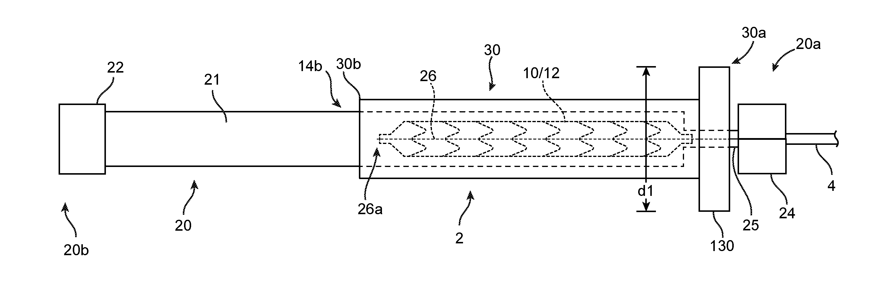
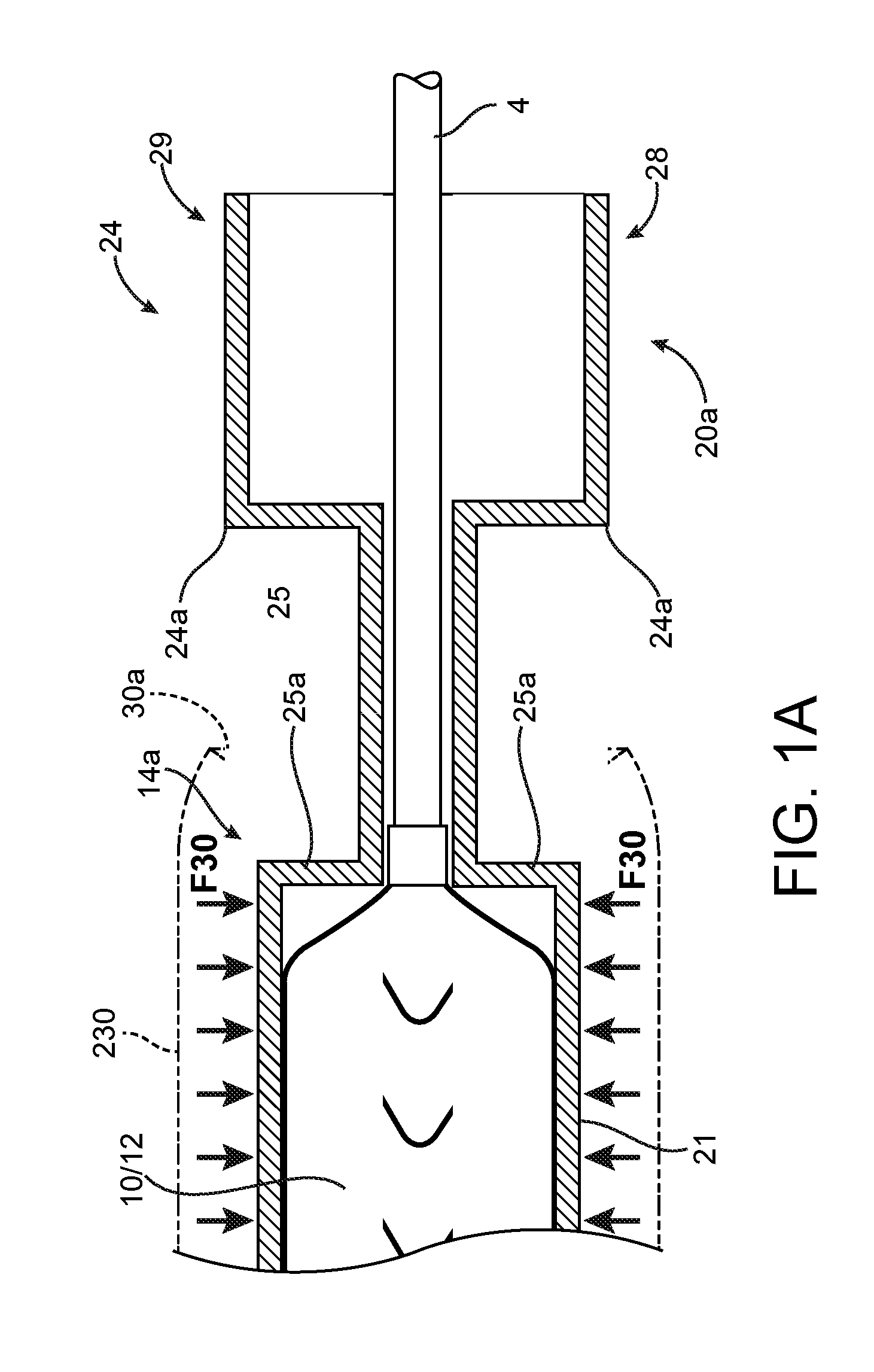
[0071]For purposes of this disclosure, the following terms and definitions apply:

[0072]The term “about” means 20%, 10%, 5%, 2% or 1% less or more than a stated value, a range or each endpoint of a stated range, or a one-sigma variation from a stated mean value. The term “substantially” refers to at least a 30%, 20%, 10%, 5%, 2% or 1% deviation from a value or range. For example, d1 substantially less than d2 means d1 is at least 30%, 20%, 10%, 5%, 2% or 1% less than d2.

[0073]The term “rigid” is a relative term used to describe something that is substantially stiffer than some other thing. For example, a first sheath or tube that is radially rigid, rigid in the radial direction, or simply rigid as compared to a second sheath or tube means that the first sheath / tube is incompressible compared to the second sheath, or essentially does not deform when an external, radially compressive force or pinching force is applied as compared to the second sheath, for the same applied load.

[0074]“I...


PUM

PropertyMeasurementUnit
Fractionaaaaaaaaaa
Fractionaaaaaaaaaa
Fractionaaaaaaaaaa

Abstract

A medical device includes a polymer scaffold crimped to a catheter having an expansion balloon. A sheath is placed over the crimped scaffold after crimping to reduce recoil of the crimped polymer scaffold and maintain scaffold-balloon engagement relied on to hold the scaffold to the balloon when the scaffold is being delivered to a target in a body. The sheath is removed by a health professional either by removing the sheath directly or using a tube containing the catheter.

Description

FIELD OF THE INVENTION[0001]The present invention relates to drug-eluting medical devices; more particularly, the invention relates to protective sheaths for scaffolds and stents crimped to a delivery balloon.BACKGROUND OF THE INVENTION[0002]A variety of non-surgical interventional procedures have been developed over the years for opening stenosed or occluded blood vessels in a patient caused by the build up of plaque or other substances in the walls of the blood vessel. Such procedures usually involve the percutaneous introduction of an interventional device into the lumen of the artery. In one procedure the stenosis can be treated by placing an expandable interventional device such as an expandable stent into the stenosed region to expand and hold open the segment of blood vessel or other arterial lumen. Metal or metal alloy stents have been found useful in the treatment or repair of blood vessels after a stenosis has been compressed by percutaneous transluminal coronary angioplas...

Claims


Application Information

Patent Timeline
IPC IPC(8): A61F2/958A61F2/82A61F2/962
CPCA61F2/958A61F2/82A61F2/962A61F2/0095A61F2/966A61F2/97A61F2002/9583A61F2210/0004A61F2250/0059A61L31/048A61L31/06A61L31/14A61L31/148A61F2/95
Inventor PACETTI, STEPHEN D.LIU, ANNIE P.JOHNSON, MARK C.
Owner ABBOTT CARDIOVASCULAR
Why Eureka
Try Eureka