
Method of producing secondary lens with hollow NANO structures for uniform illuminance

a nano-structure, uniform illumination technology, applied in the direction of instruments, lighting and heating apparatus, optical elements, etc., can solve the problems of unsuitable, diffusion or reflection, and glass material requires extremely high temperature, and achieves poor durability of materials, complicated and expensive production process

Active Publication Date: 2019-06-13
NAT CHUNG SHAN INST SCI & TECH
View PDF6 Cites 0 Cited by
  • Summary
  • Abstract
  • Description
  • Claims
  • Application Information

AI Technical Summary

Benefits of technology

The present invention provides a method for producing a secondary lens with hollow nano structures that can evenly distribute light. This improves the uniformity of the light source and increases the durability of the materials used in the special structures of the secondary optical design.

Problems solved by technology

The glass material requires extremely high temperature during the thermal process and therefore is not suitable for epitaxy packaging but for lens packaging.
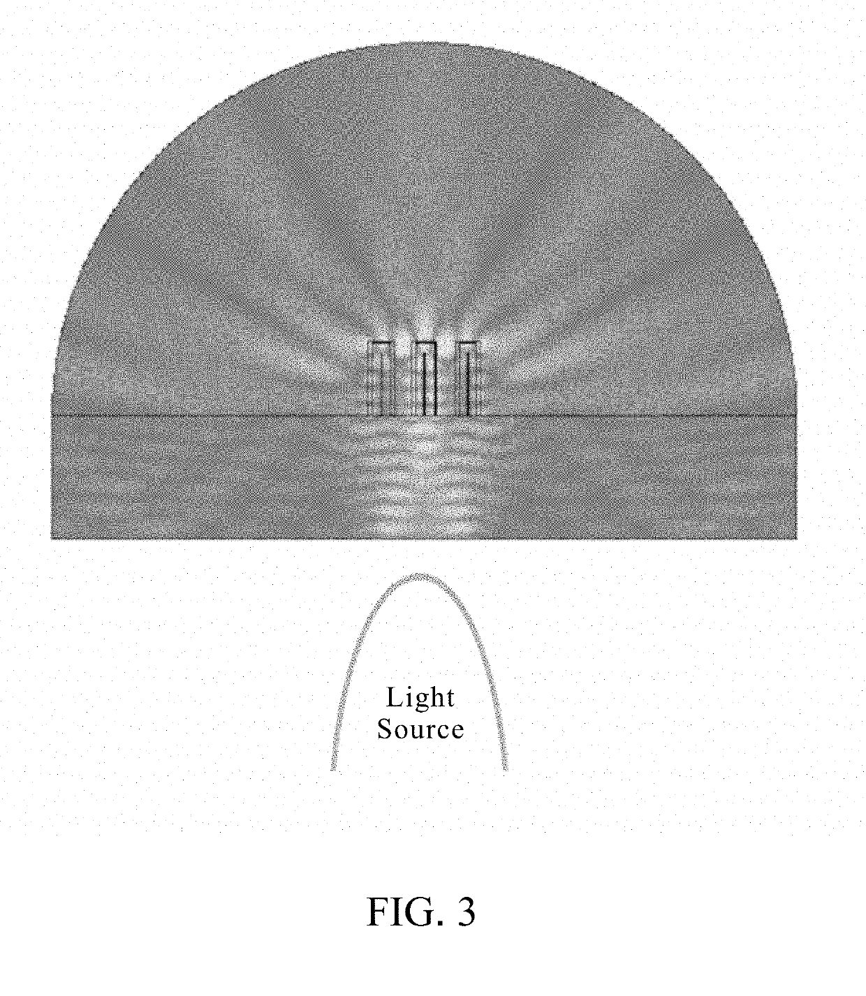
The main concept is that when light encounters the nano structure, the complete reflectivity of light is interfered by the shape of the nano structure, resulting in diffusion or reflection.
However, the disadvantage of such nano structure packaging of the secondary optical design is that the size is too huge.
If the requirement is a light source with uniform faculae, it can not be achieved simply by relying on the first optical design.
Nevertheless, the special structure in the design of the light cover or the secondary lens makes the production process relatively complicated and requires the use of injection molding to increase the production efficiency.
However, materials generally used in the injection molding are not suitable for the use of short wave light.
Light of short wave, such as ultraviolet light, will cause damages to the materials.
Therefore, light covers or secondary lenses in the secondary optical design will deteriorate and become brittle gradually as the usage time increases.

Method used


Image

  • Method of producing secondary lens with hollow NANO structures for uniform illuminance
  • Method of producing secondary lens with hollow NANO structures for uniform illuminance
  • Method of producing secondary lens with hollow NANO structures for uniform illuminance

Examples


embodiments

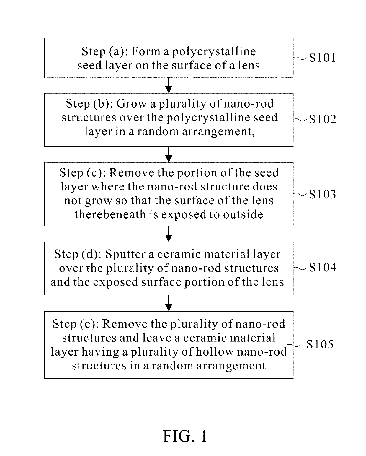
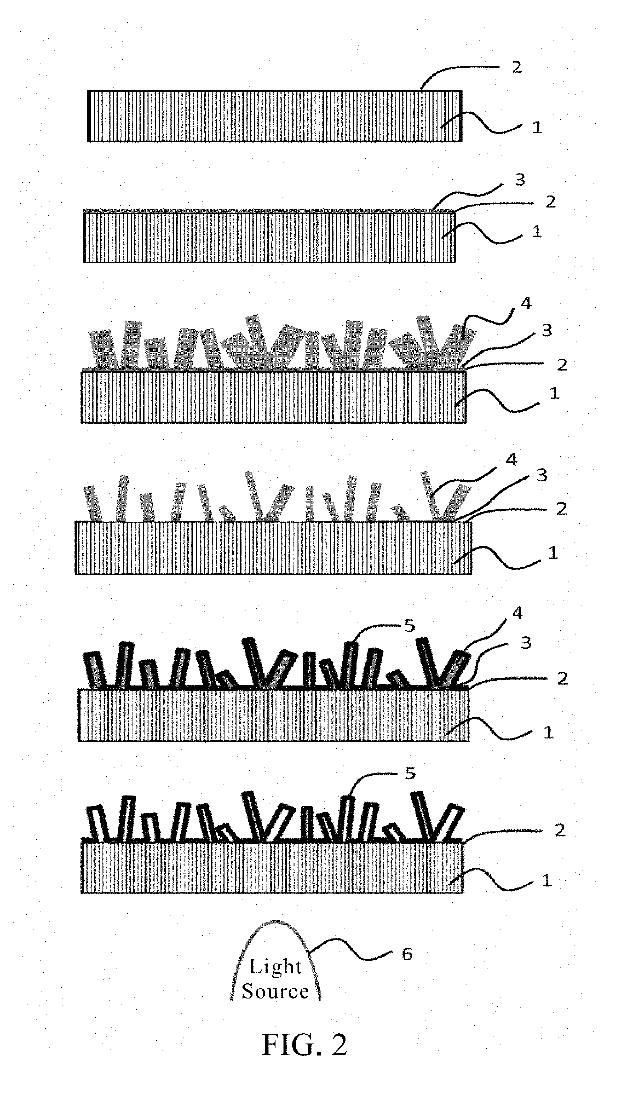
[0027]Please refer to FIG. 2. FIG. 2 is a flow chart consisting of a series of schematic diagrams of the method of producing a secondary lens with hollow nano structures for the uniform illuminance of the present invention. The steps of the embodiment of the present invention include: (a) forming a polycrystalline seed layer 3 on the surface 2 of a lens 1, wherein the lens 1 is made of high transparent materials and the lens 1 can be one of quartz, silicon dioxide, aluminum nitride (AlN), or diamond. The polycrystalline seed layer 3 can be one of zinc oxide (ZnO), aluminum doped zinc oxide (AZO), aluminum and gallium co-doped ZnO (AGZO), or indium tin oxide (ITO); (b) growing a plurality of nano-rod structures 4 over the polycrystalline seed layer 3 in a random arrangement, wherein the nano-rod structures 4 can be one of zinc oxide (ZnO), aluminum doped zinc oxide (AZO), or aluminum and gallium co-doped ZnO (AGZO); the height of the nano-rod structure 4 ranges between 1 μm˜2 μm; the...


PUM

PropertyMeasurementUnit
heightaaaaaaaaaa
temperatureaaaaaaaaaa
transmittanceaaaaaaaaaa

Abstract

A method of producing a secondary lens with hollow nano structures comprises the following steps (a) forming a polycrystalline seed layer on the surface of a lens; (b) growing a plurality of nano-rod structures over the polycrystalline seed layer in a random arrangement; (c) removing the portion of the seed layer where the nano-rod structure does not grow so that the surface of the lens therebeneath is exposed to outside; (d) sputtering a ceramic material layer over the plurality of nano-rod structures and the exposed surface portion of the lens; (e) removing the plurality of nano-rod structures and leaving a ceramic material layer having a plurality of hollow nano-rod structures in a random arrangement. A layer with hollow nano structures is formed on the surface of a lens wherein the hollow nano structures have the effect of scattering light and can improve the uniform illuminance of a secondary lens.

Description

FIELD OF THE INVENTION[0001]The present invention relates to a method of producing a secondary lens, especially a method of producing a secondary lens with hollow nano structures for the uniform illuminance.[0002]Besides challenges in epitaxy technology and element structure for ultraviolet light-emitting diode (UV LED), there are also many issues in packaging, and material selection and design for lens, such as, (1) the dependence of effective heat dissipation mechanisms to ensure the effectiveness and lifetime of the LED; the deficiency of traditional LED dissipation technology (for example, dissipation substrates, gel materials, dissipation fin designs) to cope with the applications in UV LED areas; (2) cracks and deterioration of packaging and lens materials exposed to the UV light wherein the traditional LED packaging materials are not suitable (for example, epoxy resin) due to the deterioration of illuminance, color temperature, and other optical features caused by yellowing p...

Claims


Application Information

Patent Timeline
Patent Type & Authority Applications(United States)
IPC IPC(8): C23C14/34G02B1/12F21V3/04C23C14/08C23C14/06
CPCC23C14/34G02B1/12F21V3/049C23C14/08C23C14/06G02B1/14G02B5/0226G02B5/0221G02B5/0268G02B2207/101B82Y20/00G02B5/0247G02B5/0278C23C14/024C23C14/0641C23C14/0635C23C14/5873
Inventor RUAN, JIAN-LONGHUANG, SHYH-JERKUO, YANG-KUO
Owner NAT CHUNG SHAN INST SCI & TECH
Learn More