
Method and device for the production of tubular films

Inactive Publication Date: 2005-04-14
PACIMEX VERPACKUNGEN
View PDF12 Cites 8 Cited by
  • Summary
  • Abstract
  • Description
  • Claims
  • Application Information

AI Technical Summary

Benefits of technology

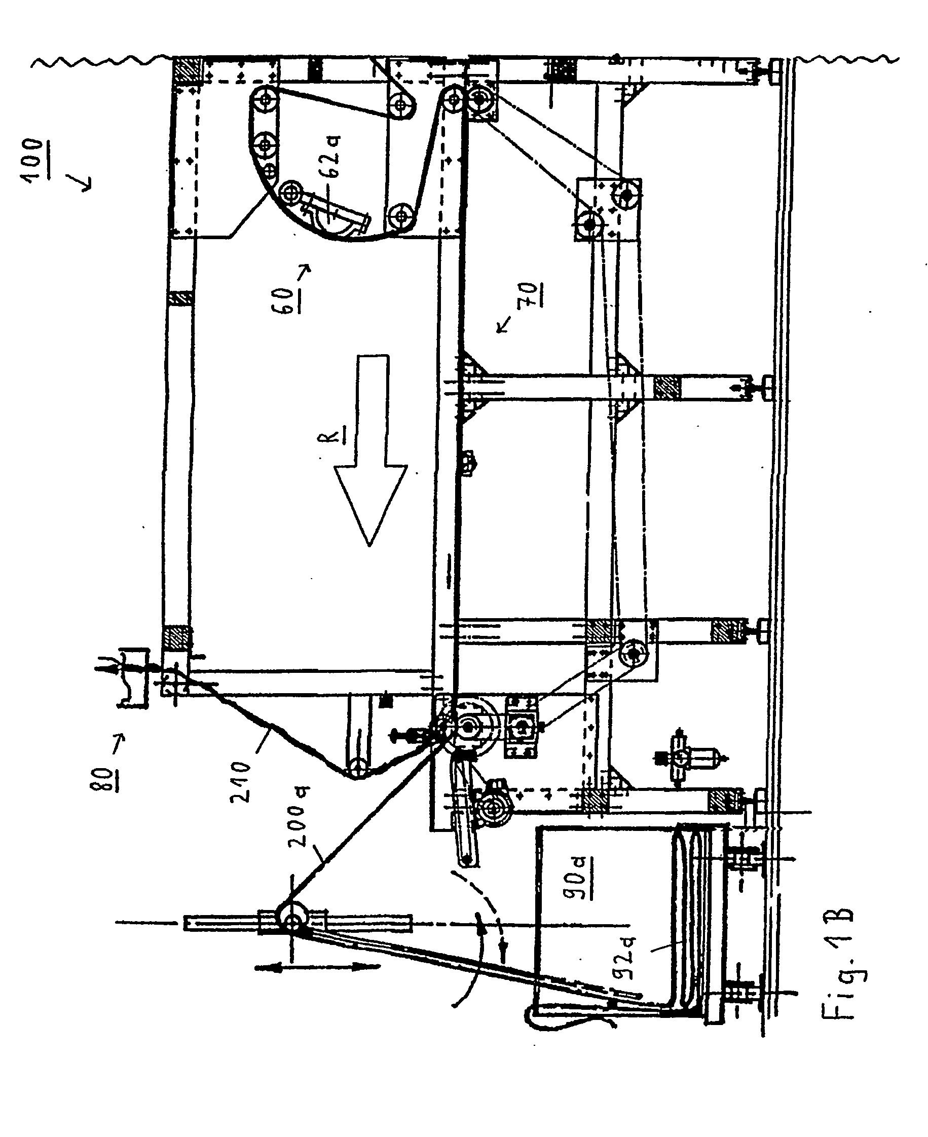
[0032] Once this film web remainder has been removed for waste, each of the tubular films formed can be received in at least one respective storage unit, in particular in at least one respective exchangeable container, in a loose zigzagged stack. Not only can such a zigzagged stack avoid tension problems in the produced tubular film, but also an air column that in accordance with experience occurs in a tubular film when pulled off via at least one pair of cores can be pushed downward, which represents another advantage of the present invention for the user (in accordance with the prior art, it was necessary to embody such take-off cores or rollers differently and to drive them differently, which rendered the production process substantially more complicated and expensive).
[0033] Additional advantageous embodiments and additional useful further developments of the present invention are characterized in the dependent claims.
[0034] Finally, the present invention relates to a novel tubular film that can be applied to an article, in particular a novel sleeve label that can be applied to a bottle, produced in accordance with the method described in the foregoing and / or by means of at least one apparatus of the type described in the foregoing.
[0035] As already explained in the foregoing, there are various options for embodying and further developing the teaching of the present invention in an advantageous manner. Additional designs, features, and advantages of the present invention are explained in greater detail in the following using the exemplary implementation in accordance with one exemplary embodiment illustrated in FIGS. 1A through 3D.

Problems solved by technology

In the past, however, the production management aspects were relatively complex during production of such tubular films.
Also, there was normally a relatively large amount of film waste during production of such tubular films, which was counterproductive both ecologically and with respect to attempts to reduce costs; thus, solutions in accordance with prior art conflicted with the trend that has been underway for some time—to achieve savings with packaging.

Method used


Image

  • Method and device for the production of tubular films
  • Method and device for the production of tubular films
  • Method and device for the production of tubular films

Examples


Embodiment Construction

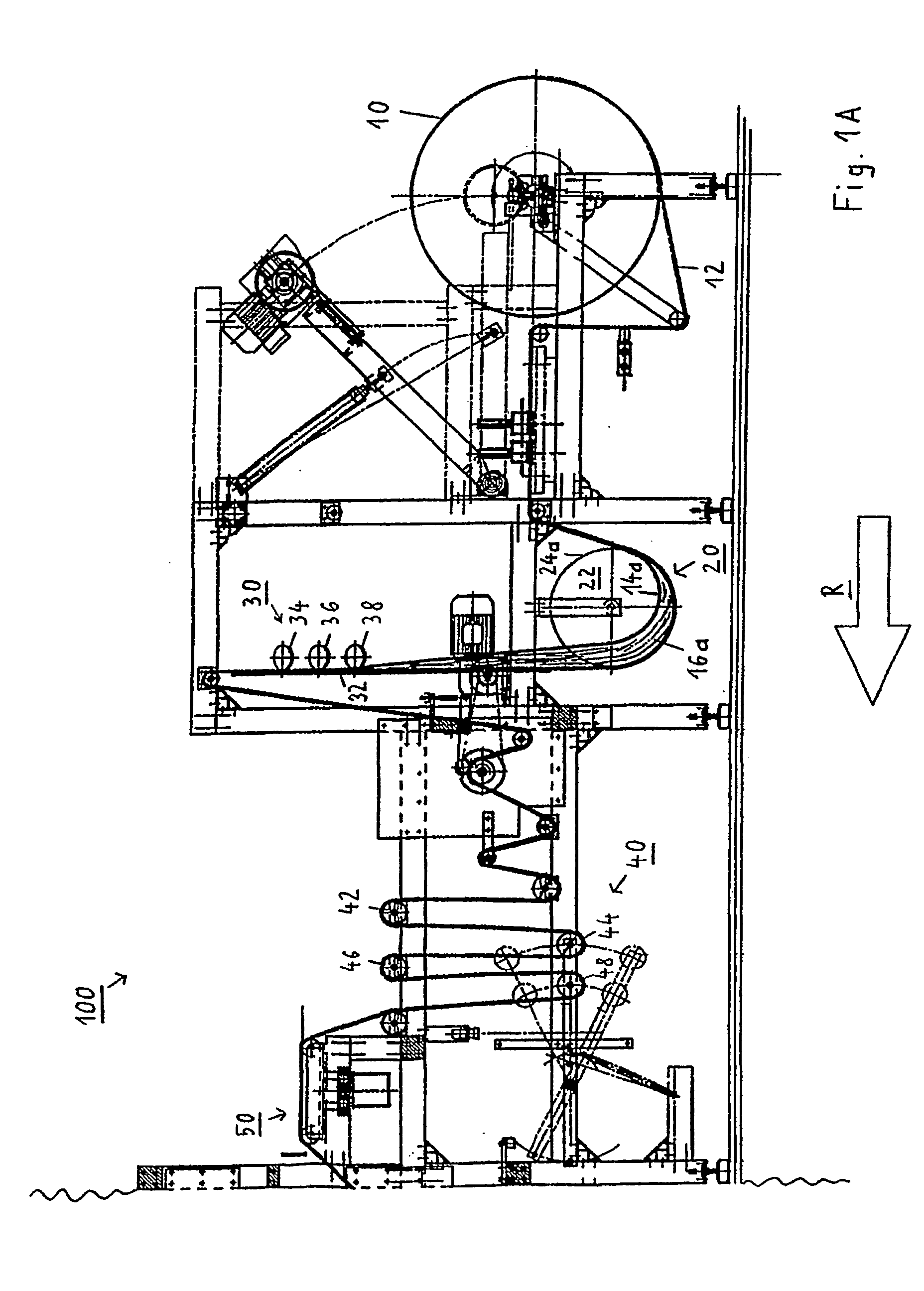
[0045] Illustrated in FIGS. 1A through 2B, the exemplary embodiment of an apparatus 100 controllable using two electrical consoles 94 and 96 (see FIG. 2A and FIG. 2B) in accordance with the present invention produces tubular films 200a, 200b (see FIG. 3D) in the form of sleeve labels that in their separated condition are applied to articles such as beverage bottles.

[0046] These tubular films 200a, 200b are produced from a film web 12 wound on a supply roller or core 10 (see FIGS. 1A and 2A), whereby this film web 12—shown in section in accordance with FIG. 3A—has two lateral regions 16a, 16b, facing the respective lateral edge 14a, 14b, and one central region 18 situated between the two lateral regions 16a, 16b.

[0047] Once the film web 12 is unwound from the supply roller or core 10, the film web 12 passes through a plurality of directional rollers or cores before it reaches a pre-folding station 20 (see FIGS. 1A and 2A). This pre-folding station 20 upwardly folds each of the two ...


PUM

PropertyMeasurementUnit
Widthaaaaaaaaaa
Tensionaaaaaaaaaa

Abstract

In order to further develop a method for producing tubular films that can be applied to an article as well as an apparatus for performing such a method, so that the complexity of production management aspects during production of tubular films is minimized and at the same time there is little material waste, the following arrangement is suggested: at least one pre-folding station for upwardly folding each of the two lateral regions of the film web along a respective bending edge that extends in the direction of travel of the film web; at least one flattening station for largely symmetrically pressing the two upwardly folded lateral regions on the central region of the film web; and, at least one welding station for forming the tubular film by means of welding the respective lateral region, in particular near the respective lateral edge, and the part of the central region spatially associated with the respective lateral region.

Description

BACKGROUND OF THE INVENTION [0001] The present invention relates to a method for producing tubular films that can be applied to an article, in particular in the form of separable sleeve labels that can be applied to bottles, from a film web, wound for instance on a supply roller or core, with two lateral regions, each facing the respective lateral edge of the film web, and with one central region situated between the two lateral regions. [0002] The present invention furthermore relates to an apparatus for performing such a method, that is, for producing tubular films that can be applied to an article, in particular in the form of separable sleeve labels that can be applied to bottles, from a film web, wound for instance on a supply roller or core, with two lateral regions facing respective lateral edges of the film web and with one central region situated between the two lateral regions. [0003] Tubular films that can be applied to articles always enjoy great popularity, because, due...

Claims


Application Information

Patent Timeline
IPC IPC(8): B29C53/36B29C53/48B29C65/02B29C65/74B31B50/64
CPCB29C53/36B29C66/4322B29C65/02B29C65/743B29C65/749B29C66/1122B29C66/137B29C66/43B29C2793/00B29L2031/744B29C53/48Y10T156/108Y10T156/1313Y10T156/1054Y10T156/1013Y10T156/1038B29C65/00B29C65/04B29C65/10B29C65/16B29C66/135B29C66/836
Inventor BRINKMANN, FRITZ
Owner PACIMEX VERPACKUNGEN
Learn More