Arrangement for implanting stent elements in or around a hollow organ

a technology for stent elements and organs, applied in the field of arrangement for implanting stent elements in or around hollow organs, can solve the problems of vascular wall injuries, stent fragment breakage and individual detachment, and stent elements can be easily damaged, so as to improve stability, facilitate the installation or placement of stent elements, and facilitate the placement

Active Publication Date: 2014-09-25
MEDIGRP
View PDF20 Cites 26 Cited by
  • Summary
  • Abstract
  • Description
  • Claims
  • Application Information

AI Technical Summary

Benefits of technology

[0007]The arrangement according to the invention is intended for installing or implanting at least one stent element in a hollow organ, especially a blood vessel. Instead of a single, more or less flexible, oblong tubular stent, it is proposed for form the arrangement according to the invention from a plurality of independent stent elements, especially short stent elements, which are arranged on an axial line, while each time a spacing is formed between neighboring elements, such that the elements can be installed or implanted without problem, individually and independently in time from each other. Thanks to the implanting of several individual stents, not connected to each other, and which are therefore freely movable independently of each other, a frictional strain on the inside of the vessels is prevented. Furthermore, it is possible to apply stents at totally different places in the body with the aid of a single catheter / kit. This not only eases the stress on the patient, but also leads to a substantial cost savings.
[0017]According to another preferred embodiment of the invention, the stent elements are detachably connected by means of spacers as a coupling element or connection anchor, which further improves the stability when placing the stent elements. Especially preferred, the particular connection can be separated by an expanding of the stent element during the implanting. For this, the connection is form-fitting especially in the axial direction, but not in at least one radial direction, so that the expansion of the stent element during the installation automatically results in a separating of the connection.

Problems solved by technology

In bendable vascular regions such as in the knee, the prostheses of the prior art have the problem that substantial pushing, pulling and twisting movements occur in the region of the bending by the stent.
Moreover, the aforementioned resulting pushing, pulling and twisting movements weaken the material webs, so that breakage and individual detachments of stent fragments can occur.
This, in turn, can lead to injuries to the vascular wall, a restenosis, for example by scar formation on the vascular wall, or even the triggering of an aneurysm.
However, an exact laying or placing of the individual stent piece is nearly impossible in this case, since such a physical separation of the stent pieces is not always uniform.
What is more, there is the disadvantage that traces of the connection elements remain on the stent pieces in place, which in turn can contribute to injury of the vascular wall.

Method used


Image

  • Arrangement for implanting stent elements in or around a hollow organ
  • Arrangement for implanting stent elements in or around a hollow organ
  • Arrangement for implanting stent elements in or around a hollow organ

Examples


Embodiment Construction

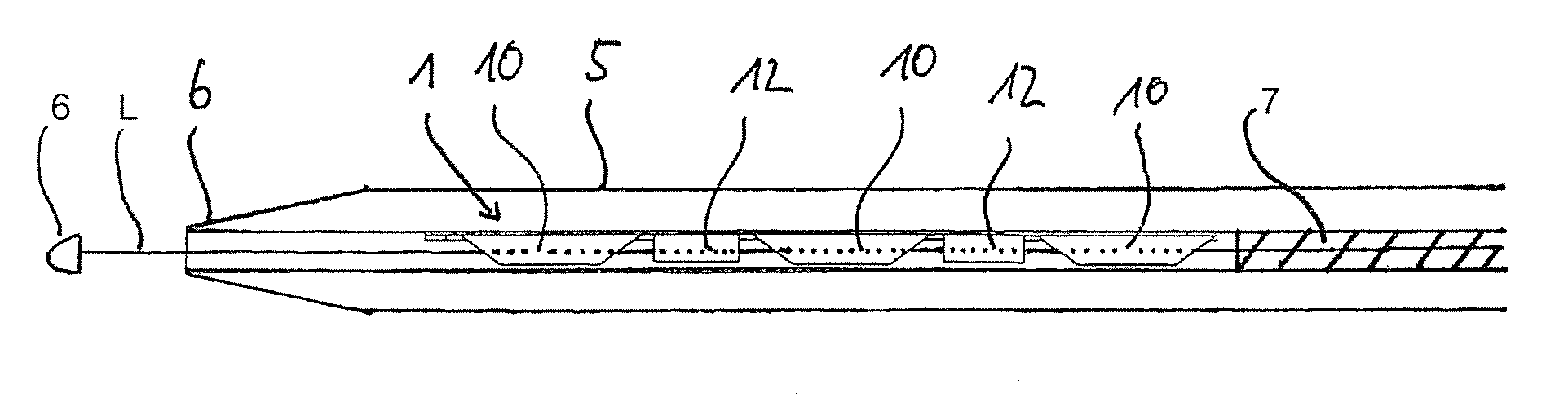
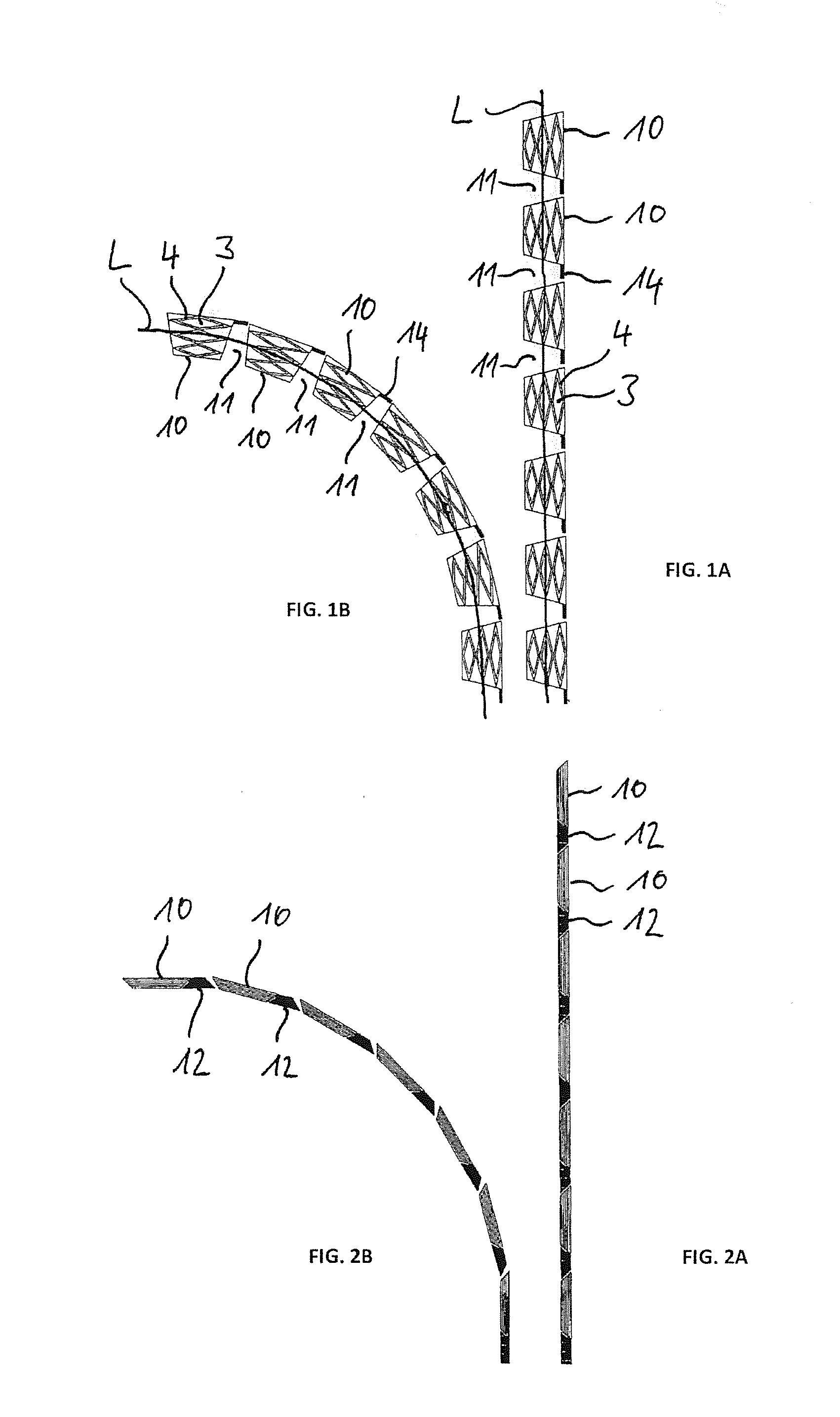
[0028]In FIGS. 1A and 1B, each time a plurality of tubular stent elements 10 are shown, which are arranged on an axial line L, the line L being straight in FIG. 1A and curved in FIG. 1B, in a side view after the implanting with the aid of the arrangement according to the invention. This makes it clear that each time a spacing 11 is formed between neighboring stent elements 10, by which the stent elements are freely movable after the implanting.

[0029]The benefit of the arrangement according to the invention is that the stent elements 10 after placement in the vessel or hollow organ are not connected together and an undulating compressed vascular inner wall during bending can escape into the free spaces 11 between the stent elements 10. This likewise prevents an irritation of the tissue, such as an excessive stress load caused by the structure of the stent elements 10, formed from material-free regions 3 and material webs 4. One can see connection anchors 14 on the stent elements 10, ...


PUM


Abstract

Arrangement for implanting stent elements in or around a hollow organ, having a plurality of stent elements, more particularly self-expanding stent elements, wherein the stent elements are arranged on an axial line (L) and wherein lateral surfaces of the respective stent elements are defined by material-free regions and material webs.

Description

FIELD OF THE INVENTION[0001]The invention concerns an arrangement for installing at least one stent element in a hollow organ, comprising a shaft with a proximal end and a distal end having an atraumatic tip, and at least one stent element arranged on an axial line inside the shaft, wherein the shaft prevents an expanding of the stent element, and a plurality of independent stent elements are arranged alongside each other on the axial line.BACKGROUND OF THE INVENTION[0002]Stents are used as prostheses for expanding and holding open in tubular hollow organs such as blood vessels. Such stents generally have a latticelike or spiral-shaped structure of material webs. Between the material webs, regions free of material are formed, which make it possible for this structure to grow into the tissue at its implantation site. Such stents are described, for example, in DE-A 197 46 88.[0003]In bendable vascular regions such as in the knee, the prostheses of the prior art have the problem that s...

Claims


Application Information

Patent Timeline
Patent Type & Authority Applications(United States)
IPC IPC(8): A61F2/962
CPCA61F2/962A61F2/966A61F2002/828
Inventor AMENDT, KLAUSJUNG, JOHANNESKOLBLE, HEINZ
Owner MEDIGRP
Why Eureka
Try Eureka